How to Manufacture a Microvisor Device
Warning
Microvisor Public Beta
Microvisor is in a pre-release phase and the information contained in this document is subject to change. Some features referenced below may not be fully available until Microvisor's General Availability (GA) release.
Manufacturing a Microvisor-based IoT product requires a single extra stage on the assembly line: to install Microvisor into the device's microcontroller, and to load your application code so that it's ready when your end-users powers up their units.
This assembly line stage also provides an ideal opportunity to load and run code which will test the newly manufactured product's hardware in order to detect component and construction failures before final assembly, packaging, and shipment.
Crucially, neither Microvisor nor your IP must be capable of being compromised at this stage. Device designers can rarely, if ever, be certain that their chosen contract manufacturer operates a secure network and plant. Security is a key Microvisor feature, so we have designed the firmware installation, test, and verification process to regard its factory environment as compromised.
Whether you are about to go into low- or high-volume manufacturing, this guide will show you how devices under test (DUTs) on the assembly line receive Microvisor and application code, and are readied for end-use. It is aimed primarily at production managers, but we recommend you share it with your team's security, QA, software, and hardware specialists.
Info
For the full, detailed factory preparation and set up sequences, please see our separate guide, The Microvisor Manufacturing Process.
A key element in the Microvisor factory process is already integrated into Microvisor-supported microcontrollers. This is Secure Firmware Install (SFI), a mechanism which allows Microvisor to be safely installed on a device in the factory.
SFI uses a secure boot environment pre-installed in the MCU silicon by its manufacturer, STMicro. Encryption keys and certificates are used to ensure that the programmer application, the code being programmed, and the MCU all trust each other, just as your web browser and a browsed site's server ensure mutual trust during an HTTPS session by exchanging and verifying certificates. Just like secure web browsing, strong encryption protects data moving between the programmer and the MCU.
When you're ready to go into production, whether for a small run or volume output, KORE Wireless will provide you with a smartcard which contains the SFI credentials and the code requires to decrypt and authorize the installation of an initial firmware image. This firmware is code which checks that the hardware is suitable for Microvisor. The card also tracks the number of installations it has been used to authorize.
The Microvisor factory process is not enabled for all accounts. To make use of the Microvisor factory process, please contact us and we will enable it for you.
To prepare for manufacturing, you first need to ready the software assets you will need. This is done locally, outside the factory.
Your application test code and your application firmware should both be packaged as Microvisor application bundles, each one generated by the Twilio CLI Microvisor plugin's apps:bundle command.
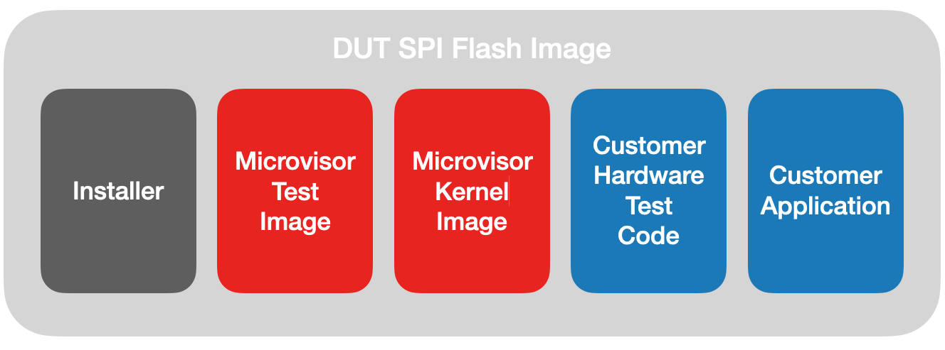
You will download a Microvisor hardware test program and a compiled Microvisor kernel. You then use the Twilio CLI Microvisor plugin's factory:image command to combine these components and your application firmware and test code into a file system image which will be written to devices' SPI flash in the factory.
You will also download a Factory VM image, which will by loaded into the factory PC and contains all the tools required to program devices' SPI flash chips and initiate the Microvisor and application installation and test sequence. A 'vagrantfile' is also provided to control the VM.
In addition, you will receive the SFI smartcard that authorizes the installation process and contains the SFI loader, which will initiate the installation process in the factory. You ship this card, along with the provisioned SFI image and the Factory VM image, to the factory.
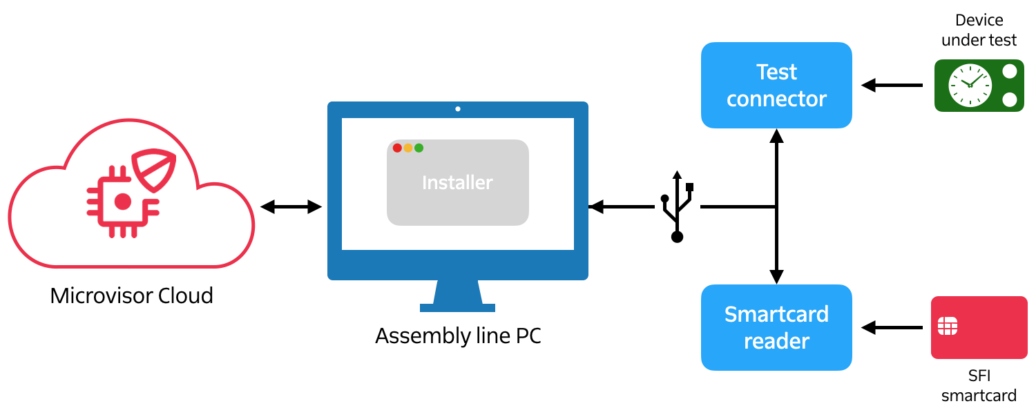
Your chosen contract manufacturer's plant will require an Internet-connected PC, a USB smartcard reader, and a USB DUT test harness which interfaces with the DUT's MCU via the latter's SWD (Serial Wire Debug) pins.
You will also need to instruct the factory to install a compatible virtualization host, such as VirtualBox, onto the PC and load it with the Factory VM image you have supplied. This runs the Installer program (part of the VM image). The Installer will instruct the operator to upload the SPI flash image to the VM via a local web browser.
The operator will also fit the smartcard into the reader.
The Microvisor factory flow takes place at a single point on the assembly line. At the start of the flow, the device's main circuit board is in a raw, insecure state; at the end it will have either been securely loaded with Microvisor and your application, or rejected as a failed unit.
During the process the code running on the MCU (first the SFI loader, then the Microvisor test program) communicates with the Installer running within the VM on the factory PC. The Installer manages the whole process. It detects the presence of a powered DUT in the test harness with an accessible SWD port, and this initiates the installation and test process for that DUT. Messages from each MCU software component allow it to report process status to the operator.
Let's go through the process step by step from the point at which a DUT reaches the station.
- The operator connects the DUT to the PC via the test connector and then powers it up.
- When the Installer detects the DUT via SWD, it programs the DUT's external SPI Flash with the file system image you created earlier. This step may be skipped if you have chosen to pre-load the SPI Flash with this file system image.
- The installer now programs the DUT's MCU with the SFI loader. It then enables TrustZone on the MCU and locks down the MCU's JTAG and SWD ports. Finally, it reboots the DUT to run the SFI loader.
- The SFI loader installs the Microvisor test program into the DUT, and then reboots the DUT to the run the test program.
- The Microvisor test program checks that the DUT is compatible with Microvisor, i.e., that all Microvisor-required hardware is present and operating correctly. If any tests fail, this is signaled via the Installer on the PC, and the flow ends. The operator can remove the device from the line. Error information is relayed back to the PC via the test harness.
- If the Microvisor tests pass, the Microvisor test program generates the DUT's unique ID from the MCU's chip ID and establishes a public and private key pair. These are used to create a certificate signing request (CSR) containing the DUT ID. The CSR is signed first by the DUT's private key and secondly by the Microvisor test program.
- The CSR is sent securely to the Microvisor Cloud over the assembly line PC's Internet connection. The Microvisor Cloud associates the DUT with your account and returns the requested certificate, which is stored on the DUT.
- Finally, the Microvisor test program installs Microvisor itself onto the DUT and then reboots the DUT.
- The standard Microvisor startup flow now occurs, at the end of which Microvisor loads your hardware test code, which is implemented as a standard Microvisor application bundle, from the DUT's external SPI flash. Your test code will subsequently signal success or failure in its own way, allowing the operator to remove the device from the line if necessary.
- If your hardware tests pass, your test code signals this to Microvisor with a system call. This causes Microvisor to copy your application firmware from SPI Flash into the MCU, overwriting your test code, and to signal success.
The board can now continue along the assembly line to be encased, packaged, and prepared for shipment from the factory.
Peripherals required by Microvisor need to be checked to ensure that they are soldered correctly, are operational, and meet the required specification. These tests, performed by code supplied by KORE Wireless, involve powering up radios and checking communication paths. The cellular modem, if present, is tested to ensure it is visible to Microvisor and that its SIM is accessible. The WiFi sub-module, also if present, is booted and checked that it can see any local networks. The QSPI is checked to make sure that it's the correct size and correctly responds to certain access commands.
This stage is entirely up to you to design. It offers a great opportunity to run tests on all the key elements of your hardware: peripheral buses, sensors, actuators, displays, and so on. You may choose to implement a second test harness that is geared toward the tests you wish to perform, or make use of the Microvisor test and installation harness.
Your engineering team will develop your application's factory test code alongside the development of the application itself and the board design work. The test code is simply a Microvisor application bundle that you have coded for the purpose. However, it is installed directly to each DUT's external SPI Flash, either in the factory or before the SPI Flash is soldered to the PCB, via the SPI flash image you generate ahead of production.
You may choose to transmit test log data via the harness back to code running on the factory PC so that test progress can be monitored by an assembly line operator, to prompt them to observe expected behavior, or to trigger actions that will be detected by the test code. This will require software, either developed by you or a third-party, that will run on the assembly line PC outside of the Factory VM provided by KORE Wireless.
When your code has run all of its tests, it makes the System Call mvTestingComplete(), passing in an integer to indicate the outcome of the tests: zero for success, or any other value for failure. On success, Microvisor will replace your test code with your application firmware.
The Microvisor test connector is USB-to-UART bridge hardware that allows the Installer running within a VM on the factory PC to communicate with the DUT's MCU. Typically, the connector will feature an FTDI chip or similar between the connector's USB port and links to a handful of STM32U585 GPIO pins, which are listed below. These pins are used to support a provisioning UART and SWD (Serial Wire Debug). SWD is used for programming; UART for relaying installation status messages to the host.
How you arrange these links is up to you. You might, for example, include a ten-pin SWD connector on your product's motherboard, with the data, clock, reset, power and ground pins wired to the relevant pins. Or you may opt to connect the MCU's pins to pads against which test connector pogo pins will connect. The choice is yours: select a solution which best balances convenience, accessibility and cost for your product and factory.
The following STM32U585 pins are reserved by Microvisor for SWD:
| SWD Role | STM32U585 Pin |
|---|---|
| SWDIO | PA13 |
| SWCLK | PA14 |
| SWO | PB3 |
| RESET | NRST |
An SWD connector will also require 3V3 and GND connections. A connector's KEY pin need not be connected in this case.
The following STM32U585 pins are reserved by Microvisor for the provisioning UART:
| UART Role | STM32U585 GPIO |
|---|---|
| RX | PE4 |
| TX | PB0 |
For the full, detailed factory preparation and set up sequences, please see our separate guide, The Microvisor Manufacturing Process.
Info
Microvisor Help and Support
We welcome all inquiries you may have about Microvisor and its implementation, and any support questions that arise once you've begun developing with Microvisor. Please submit your queries via a KORE Wireless ticket: log in to the Kore console and click the Contact Support button in the left-hand navbar.