The Microvisor Manufacturing Process
Warning
Microvisor Public Beta
Microvisor is in a pre-release phase and the information contained in this document is subject to change. Some features referenced below may not be fully available until Microvisor's General Availability (GA) release.
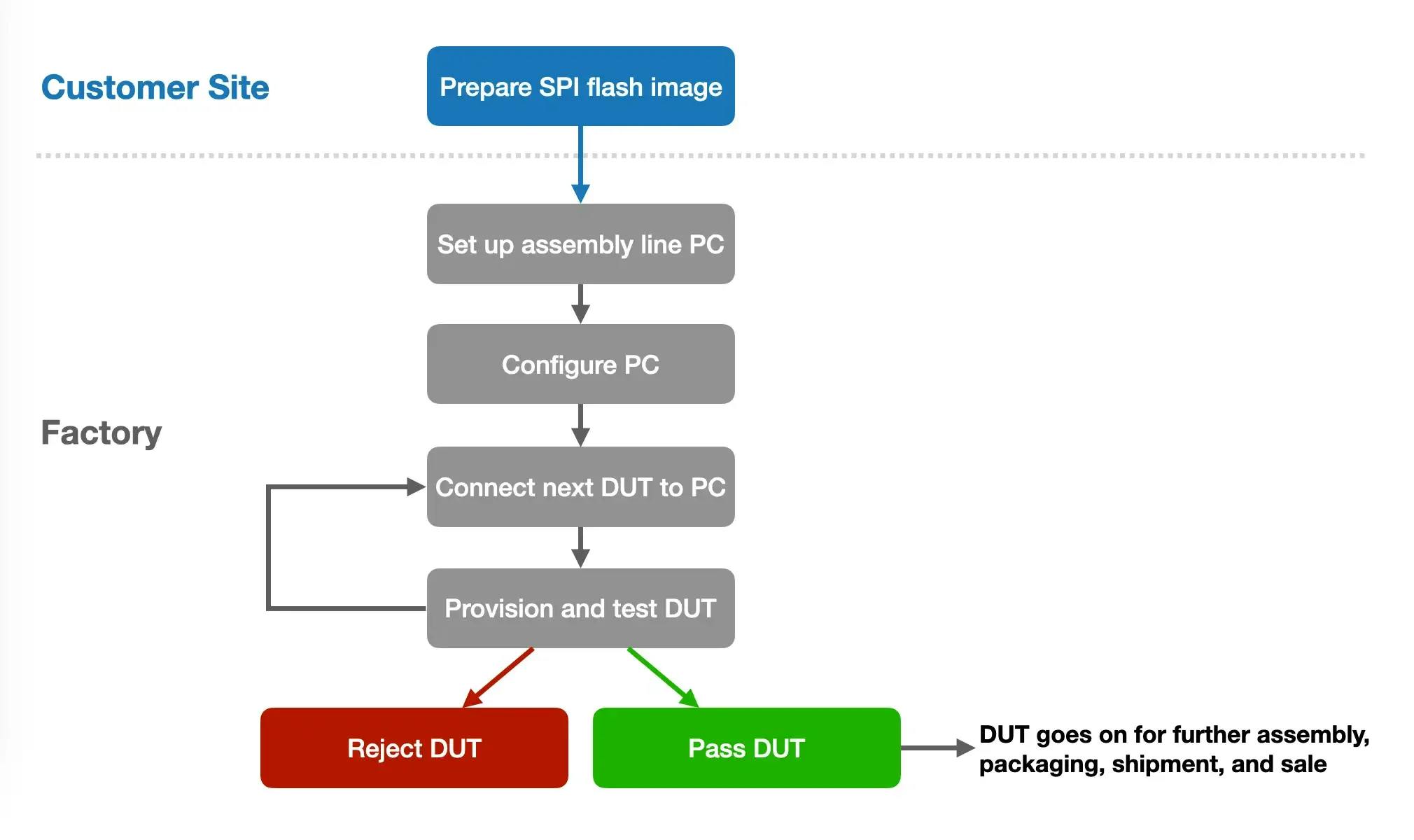
This guide will walk your through the Microvisor Factory Process, the procedure by which a 'raw' STM32U585-based device is provisioned first with Microvisor and then your production application firmware.
The procedure we will follow below is also the one we ourselves use to install Microvisor onto new Microvisor Nucleo Development Boards for beta program participants.
The PC set up at the start of the process is the assembly line station at which Microvisor and your application are securely installed into each device under test (DUT). Tests are run to verify the operation of the hardware that Microvisor requires, and the hardware used by your application.
Info
We recommend that your acclimatize yourself to the Microvisor Factory Process before you designing and developing your connected product. You can try out the flow using a standard Microvisor Nucleo Development Board (NDB) in place of the DUT.
When you come to the Program your DUT section, you will need to perform a few extra steps in this case. Specifically, the NDB has already been programmed with Microvisor, so must be inlocked before the factory installer can providsion Microvisor to it. The Program your DUT section includes instructions to show you how this can be achieved.
- A PC running Ubuntu Desktop 22.04 .
- Oracle Virtual Box 6.1.50 or above installed on the PC.
- Oracle VirtualBox Expansion Pack for 6.1 installed on the PC.
- Vagrant installed on the PC.
- A Twilio account.
- A Twilio API key and API secret. These can be obtained from the Twilio Console in the Account > API keys & tokens section. We strongly recommend that you create a fresh key, of the type Restricted , and secret specifically for this purpose, and that you revoke keys when assembly is complete.If your console does not allow you to create Restricted keys, please submit a Twilio Help Center ticket Additionally, please ensure that you record the newly created key and secret pair as it will not be possible to retrieve them later. Revoke the old one if you forget it and create a new pair.
- A local WiFi network. This must use the 2.4GHz band and be compatible with the 802.11b/g/n standards.
- A local Ethernet network (or direct connection to a spare Ethernet port on the LAN router). The router must include a DHCP server (typically part of the router).
- An Ethernet cable.
- A data-capable Micro USB cable. Choose carefully: some cheap ones support power only.
- An STMicroelectronics STM32HSMv2 HSM smartcard. This has to be programmed by KORE Wireless. Please contact support@microvisor.com to request one.
- A USB smartcard reader.
- An STMicroelectronics STLINK-V3MINIE . Widely available from electronics suppliers. You will also need a USB-C male adapter to connect this to the factory PC.
To install Virtual Box, please download version 6.1.50 and its Extension Pack from the Virtual Box downloads page and follow these instructions. Once the install has completed, run the following commands in a terminal:
-
sudo usermod -a -G vboxusers $USER -
sudo shutdown -r now
Unlike regular application deployments, factory-provisioned application firmware is delivered via the SPI flash image copied to the DUT during the provisioning process. Your application test code is also incorporated into the image, along with Microvisor itself and the Microvisor hardware test code, both of which you can obtain from the links below.
Info
If you are assessing the factory process and using a Nucleo development board as your DUT, you can download, build, and bundle our FreeRTOS demo as your application firmware.
You will also need to create an application test bundle, but this is straightforward: clone our App Test Demo repo, which will build a suitable (but of limited functionality) app test bundle that can be consumed in step 2, below.
Now use the Twilio CLI Microvisor plugin to build your SPI flash image. You will need to be signed in to the Twilio CLI on the computer used to generate the image:
-
Create an app bundle:
_10twilio microvisor:apps:bundle /path/to/compiled/app/bin \_10/path/to/app/bundle/zip -
Sign the app bundle:
_10twilio microvisor:apps:create /path/to/app/bundle/zip \_10--bundle-out /path/to/signed/app/bundle/zip -
Create an app test bundle:
_10twilio microvisor:apps:bundle /path/to/compiled/app/test/bin \_10/path/to/app/test/bundle/zip -
Sign the app test bundle:
_10twilio microvisor:apps:create /path/to/app/test/bundle/zip \_10--bundle-out /path/to/signed/app/test/bundle/zip -
Assemble the image:
_10twilio microvisor:factory:image \_10--application /path/to/signed/app/bundle \_10--application-test /path/to/signed/app/test/bundle \_10--microvisor /path/to/downloaded/kernel \_10--microvisor-test /path/to/downloaded/test \_10/path/to/write/spiflash.img.bin
You now need to send your spiflash.img.bin file to your manufacturer for use when they reach step 5 of Configure the Assembly Line PC.
This needs to be performed only once. The PC can then be used to prime multiple DUTs one after the other, across multiple production runs.
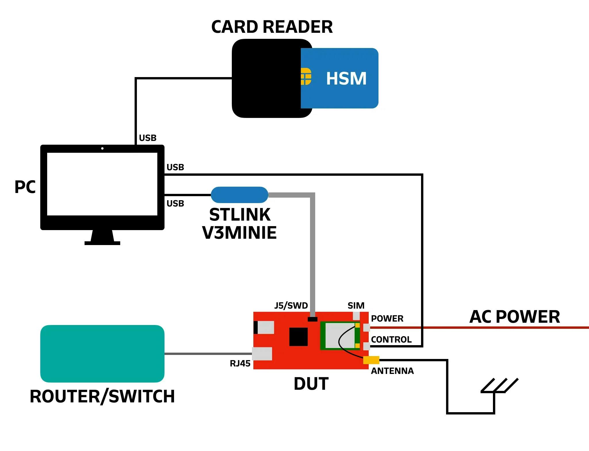
- Connect the smartcard reader to the PC.
- Insert the smartcard into the reader.
- Connect the STLINK-V3MINIE to the PC via the male USB-C adapter.
- Connect the Micro USB cable to the PC.
Steps 1 through 8 need to be performed only once. Steps 9 and up will need to be followed every time the PC is power-cycled.
- Start up PC and log in to Ubuntu.
- Open the Terminal application (press ctrl-alt-t ).
-
In the Terminal, run:
_10mkdir $HOME/factory -
In the Terminal, run:
_10cd $HOME/factory -
Download the Microvisor VM
, which will be of the form
microvisor_factory.tar.gz. - Download the accompanying Vagrantfile .
-
Copy the SPI flash image
spiflash.img.binto the$HOME/factorydirectory. -
In the Terminal, run:
_10vagrant box add --name microvisor_factory microvisor_factory.tar.gz -
In the Terminal, run:
_10lsusbLocate the HSM reader’s two ID values and note them down.
- Open Virtual Box and navigate to Settings > USB > USB Device Filters . There should be four devices listed, including the HSM reader. Make sure its HID/VID match the two values you noted down in step 8. If they are not, change the values to match those you noted down. IMPORTANT Restart Virtual Box to make sure the changes take effect.
-
In the Terminal, run:
_10vagrant up -
Open
Firefox
and enter
localhost:8080into the address field, then hit Enter . - Under API Credentials , enter your Twilio account's restricted API key and secret, and click Save .
-
Under
SPIFlash Image
, click
Browse...
, locate the SPI flash image
spiflash.img.binon the PC, and click Upload . -
If
smartcard not presentis shown under HSM Status , check that the smartcard reader is connected to the PC and that the smartcard is inserted, then click the first Refresh button. When the HSM is ready, you will see its state, firmware version and the number of remaining device licenses it contains.
This sequence will need to be followed for each DUT being provisioned.
Warning
Make sure you connect power last. The other connections must already be in place when you do.
- Insert the Super SIM into the DUT's SIM slot.
- Connect the STLINK-V3MINIE to the DUT's J5 header using the gray ribbon cable supplied with the STLINK-V3MINIE. On the Nucleo development board the header is also labelled SWD .
- Join the router and the DUT with the Ethernet cable.
- Connect the Micro USB cable to the DUT's provisioning port. This is marked as CONTROL on the Nucleo, but may be marked differently on your own product.
- Connect the cellular antenna.
- Connect the DUT's POWER port to the supplied USB-C power adapter.
- Check the STLINK/Device Status section in the web browser UI. If there is no information listed, check the STLINK's connections to the PC and the DUT, and click the second Refresh button.
The sequence must be followed for every DUT being provisioned.
- In the web browser UI click PROGRAM DEVICE .
Info
If the PROGRAM DEVICE button is deactivated, it means that the DUT has already been programmed. This will likely be the case if you are using a Nucleo development board as a DUT to test the factory process. You will need to unlock the DUT before proceeding. Unlocking the DUT temporarily removes the STM32U585's RDP (Readout Protection) control; it will be re-enabled when the DUT is re-programmed.
- Click UNLOCK DEVICE in the web browser UI.
- The progress of the unlock operation will appear on the screen.
- When you are prompted to power-cycle the DUT, remove the USB-C power cable from the DUT (not the AC adapter), wait a moment and then re-connect it.
- Click CONTINUE .
- When the process completes, the DUT is ready to program.
- Click PROGRAM DEVICE .
The installer will check that it can contact the Microvisor cloud and verify your Twilio API credentials. If these checks fail, installation will halt, the cause will be reported in the web browser UI. If the checks pass, the SPI flash image will be copied to the DUT.
Now reconnect the USB-C power cable.
An on-board hardware test will now take place, checking the cellular modem, the SIM card, and WiFi and Ethernet connectivity.
The provisioning script will communicate with the Microvisor Cloud to receive a valid device-specific certificate which will be stored on the DUT.
Next, an on-board application test will take place.
The DUT is now programmed with Microvisor and ready for packaging, shipment and use.
The assembly line operator can now pass the DUT on to the next stage of assembly and place a new DUT in the station: start again at Set up the DUT.
Info
Microvisor Help and Support
We welcome all inquiries you may have about Microvisor and its implementation, and any support questions that arise once you've begun developing with Microvisor. Please submit your queries via a KORE Wireless ticket: log in to the Kore console and click the Contact Support button in the left-hand navbar.