Design IoT Devices with Microvisor
Warning
Microvisor Public Beta
Microvisor is in a pre-release phase and the information contained in this document is subject to change. Some features referenced below may not be fully available until Microvisor's General Availability (GA) release.
This guide will provide the hardware designer with all the information they need to successfully integrate an STM32U585 microcontroller with Microvisor on board into their own IoT products, whether that's a new design or an update to an existing product.
Microvisor works with the ST Micro STM32U585 MCU so we recommend that you keep the STM32U585 datasheet nearby while reading this document. We also recommend that you consult the Microvisor Nucleo form-factor development board reference design, which provides a working example of a Microvisor-based product. In particular, use the board's schematics, Altium and Gerber files , for guidance on designing your own Microvisor hardware.
The following diagram illustrates the core components of a typical Microvisor-based IoT product:
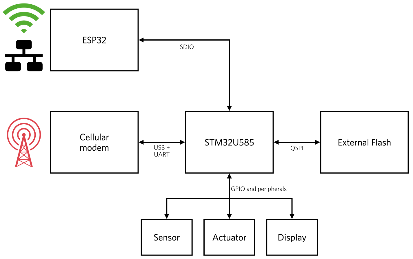
At the device's center is the STM32U585 MCU. It uses the external flash as a staging area for Microvisor and application updates. Any space beyond the staging area is made available to the application. Connectivity is provided by a cellular module, such as the Quectel EG-21, and/or the Espressif ESP32 WiFi+BLE module. The ESP32 also supports wired network connections. Additional, application-specific hardware is connected through the STM32U585's GPIO and standard buses (SPI, I²C, I²S, UART).
Info
This represents the initial selection of qualified networking modules. We expect to support further options in due course according to customer demand.
In addition to the STM32U585 MCU, Microvisor-based IoT products will require the following components:
An external 64Mbit (8MByte) or greater SPI flash part is mandatory. The address space above 0x600000 (6MByte) is expected to be made available to your application via future Microvisor system calls. The area below this address will be erased and reprogrammed by Microvisor, so applications using pre-programmed SPI flash components must not use any space below this address.
The following SPI flash parts are directly supported:
| Part Name | Chip ID | Voltage Range | Quad-read supported |
|---|---|---|---|
| Macronix MX25R6435F | C2-28-17 | 1.8-3.3V | Yes |
| Cypress S25FL064L | 01-60-17 | 2.7-3.3V | Yes |
| Winbond W25Q64JV | EF-40-17 | 2.7-3.3V | Yes |
Other SPI flash chips should also work with Microvisor, although in 1-bit-wide mode only, provided that they:
- Are at least 64Mbit (8Mbyte) in size.
-
Support 4, 32 and 64Kbyte erases (commands
0x20,0x52,0xD8). -
Either support deep-power-down using commands
0xB9(sleep) and0xAB(wake), or ignore those two commands.
Add an external crystal connected to the Low-Speed External (LSE) clock source.
The crystal is connected between the STM32U585's OSC32_IN and OSC32_OUT pins.
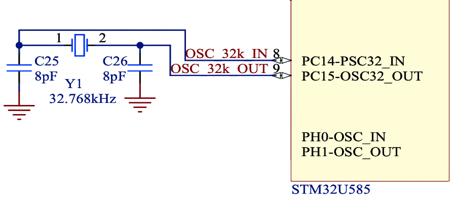
The LSE crystal is used to calibrate the High-Speed Internal (HSI) oscillator which drives the CPU core and all peripheral clocks. For this reason, it's important to ensure the 32kHz oscillator is correctly tuned to be accurate within the crystal specification.
Please see ST Application Note AN2867 for crystal selection and implementation details.
Microvisor initially supports the Quectel EG21-G LTE Cat 1 cellular module for mobile connections to the Internet. It has global band support. Microvisor will reserve this module's networking functionality, and the application must establish cellular Internet communications via Microvisor system calls.
The application will have full access to the EG21-G for GNSS (GPS, GLONASS, BeiDou/Compass, Galileo, and QZSS) operations.
Warning
GNSS will not be available in the Microvisor Public Beta phase.
In addition to the modem, you will need to incorporate a slot for a card form-factor SIM, or an MFF2 embedded SIM. Microvisor will provide out-of-the-box support for KORE Wireless Super SIM. Other SIMs may also be supported over time according to customer demand.
Microvisor will initially support the Espressif ESP32-WROOM-32E WiFi+BLE module as a communications co-processor for WLAN connections to the Internet. If this module is the device's primary route to the Internet, Microvisor will reserve its WiFi functionality, and the application must establish WLAN Internet communications via Microvisor system calls. The ESP32 firmware and stack is provided by Microvisor.
The application will have full access to the ESP32 for BLE operations, and full access to the WiFi subsystem for local networking.
Warning
BLE will not be available in the Microvisor Public Beta phase.
The Espressif ESP32 module also provides Ethernet support. If this is to be the device's primary route to the Internet, Microvisor will reserve its Ethernet functionality, and the application must establish Internet communications via Microvisor system calls. The ESP32 firmware and stack is provided by Microvisor.
The application will also have full access to the Ethernet subsystem for local networking.
Devices which offer WiFi connectivity will need at some point to be provisioned with local WiFi network credentials. The ESP32 WiFi module supported by Microvisor also incorporates BLE functionality, and it is expected that your application will use BLE to receive WiFi credentials and other setup information, such as HTTP proxy settings or static network configuration, from a companion mobile app.
This provisioning functionality is not provided by Microvisor itself, but your application will need to pass WiFi settings to Microvisor so that it can enable Internet connectivity via WiFi. This will be done through a Microvisor system call.
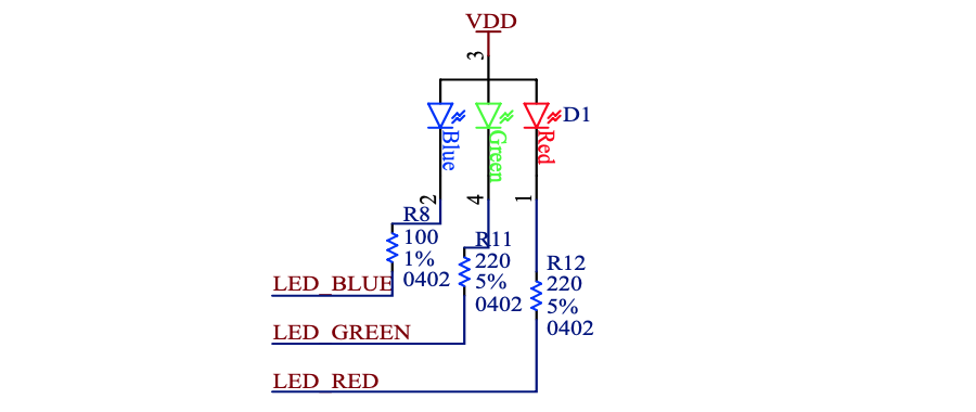
Microvisor requires the inclusion of a tri-color (red, green, and blue) LED. It is used to indicate different device and network connection states. Situations such as the device's external SPI flash being inaccessible at start-up, or Microvisor can't connect to WiFi using stored credentials, will be signalled with a sequence of colours blinked on the LED.
In addition to the mandatory hardware components, we recommend you incorporate the following components and sub-systems in your design.
To provide users with a reset button, connect the STM32U585's NRST pin to a switch which will connect NRST to GND when pressed. In the reference design, for example, RESET_L connects to NRST:

Warning
At this time, reset behavior is undefined.
STM32U585 GPIO pin PC6 is reserved for the Microvisor Rescue pin. We intended to provide a mechanism to allow, say, a button connected to this pin to be used to recover devices from undefined states during development, or to bypass certain functionality during the start up of production devices. At this time, the Rescue pin behavior has yet to be defined.
On the Microvisor Nucleo Development Board this is connected to VDD via header W6.
Microvisor supports the STMicro STM32U585 MCU, a new MCU that supports the ARMv8-M architecture's TrustZone technology. TrustZone establishes two separate operating domains: the 'trusted' Secure World (SW) and the 'untrusted' Non-secure World (NSW). Microvisor is pre-installed on pre-release hardware and operates within the privileged Secure World; your application will be stored in and run from the Non-secure World. TrustZone completely isolates the two domains, each of which has its own Memory Protection Unit (MPU), Nested Vector Interrupt Controller (NVIC), and Direct Memory Access (DMA) controller.
Every application has complete access to all of the host device's hardware resources with the exception of cloud-facing network interfaces and a handful of the STM32U585's peripherals (see below). The application can access the unreserved peripherals at the memory locations detailed in the STM32U585 datasheet, or by calling functions provided by a hardware abstraction layer (HAL) library.
Applications can rely on Microvisor to provide the secure cloud tunnel, or operate through a virtual network interface provided by Microvisor.
Applications which use network interfaces that are not cloud facing — for example, ZigBee or LoRA gateway products — are totally in control of those interfaces. Microvisor has no access to them.
Microvisor reserves the following STM32U585 peripherals:
| STM32U585 Peripheral | Reserved For |
|---|---|
RCC | The STM32U585's reset and clock controller |
RNG, AES, SAES, HASH, PKA | The STM32U585's true random-number generator, used to make secure TLS network connections and for other security functions |
RTC | The STM32U585's real-time clock. Microvisor owns the RTC, because it has to control when and whether the STM32U585 enters the deep-sleep Standby mode |
TIM3 | The System LED PWM timer |
TIM5 | The Microvisor system timer |
PWR | The STM32U585's power controller |
DCACHE, ICACHE, RAMCFG, WWDG, IWDG | System management |
OCTOSPI1, OCTOSPIM | The STM32U585's interface to the external QSPI, used to securely store upgrade Bundles |
OTG_FS, LPUART1 | Used for communications with the cellular modem |
SDMMC1, UART5 | Used for communications with the WiFi+BLE module |
DCMI | The digital camera interface. This is currently reserved by Microvisor but may become free in a future update |
We also reserve three EXTI lines: GPIO8, GPIO9, and PVD.
The STM32U585 is expected to be made available in LQFP100, UFBGA132, and LQFP144 packages. Please see the STM32U585 datasheet for pinout and ballout schematics.
All pins default to tristate high impedance (floating) at power up and while the STM32U585 is in low power deep sleep.
Microvisor reserves a number of STM32U585 pins for essential system usage, i.e., to enable the peripherals described above. These pins include:
-
PA4,PD4,PC0,PC2,PC3,PE10— connection to the QSPI flash. -
PC8-PC12,PD2— SDIO connection to the WiFi+BLE module. -
PA11,PA12,PE7— USB connection to the cellular module. -
PG3-PG8—LPUART1connection to the cellular module. -
PE8— cellular modemRING. -
PD14— cellular module power enable. -
PD15— WiFi+BLE module power enable. -
PC6— Rescue pin -
PE3,PE5,PE6— Tri-color LED . -
PE4,PB0— provisioning UART
For 3V3 applications alternate GPIO pins can be used for the cellular UART: PA6, PA15, PB1, PB10, PC1, PC7.
Info
The pin names listed above are those of the LQFP144 package. These pin reservations will be updated in due course for other STMU585 packages as they are verified.
Pins PE4 (RX) and PB0 (TX) are used as a UART for provisioning WiFi credentials and obtaining device information. If PE4 is asserted at boot, Microvisor suspends application operation and will only operate to provide the console with which you interact over the UART. Microvisor will return to normal operation only when rebooted while PE4 is not asserted.
For example, the Nucleo Development Board is configured so that PE4 is asserted at boot when the board is connected to a host PC via the CONTROL micro USB port.
The provisioning UART is intended primarily for use during application development, but it is also used during the Microvisor factory provisioning process. Production devices must not make use of the UART's pins at this stage, but may do so once they have been provisioned with Microvisor and their application firmware, and have successfully passed your application-level tests on the assembly line. However, you must ensure that PE4 is correctly gated to prevent it being asserted at boot and triggering the provisioning UART — your application code will not start in this case.
Access to STMicro documentation may require signing in to the STMicro website.
Please see the changelog.
Info
Microvisor Help and Support
We welcome all inquiries you may have about Microvisor and its implementation, and any support questions that arise once you've begun developing with Microvisor. Please submit your queries via a KORE Wireless ticket: log in to the Kore console and click the Contact Support button in the left-hand navbar.