Works with Super SIM: Quectel EG25-G
The Quectel EG25-G module supports LTE Cat 4 (4G), UMTS/HSPA+ (3G), and GSM/EDGE/GPRS (2G) cellular connectivity, and features integrated GNSS. Optimized for broadband IoT applications requiring very high bandwidths. The EG25-G provides data rates of up to 150Mbps down and 50Mbps up.
Info
Learn more about the EG25-G on the Quectel website.
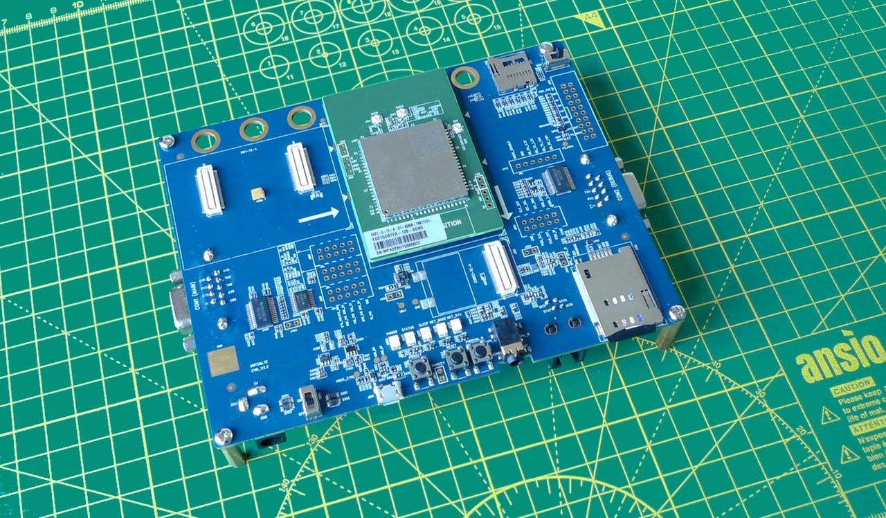
The best way to begin working with the EG25-G is to take advantage of Quectel's UMTS & LTE EVB developer kit. It features powerful and easy‐to‐use tools in an environment specifically designed for the development and testing of cellular and GNSS applications based on any of a variety of Quectel modems, including the EG25-G. Just clip on a test board featuring the modem you're using. The one you need for this guide is the EG25-G-TE-A test board. It's available separately. The kit can be connected to and used with a Windows 10, Linux or macOS computer.
The EVB and the separate test board can be purchased from the following suppliers:
Info
Working with the EVB and EG25-G requires a configured Super SIM. If you haven't set up your Super SIM in the Console, please do so now. The Super SIM First Steps guide has help if you need it.
-
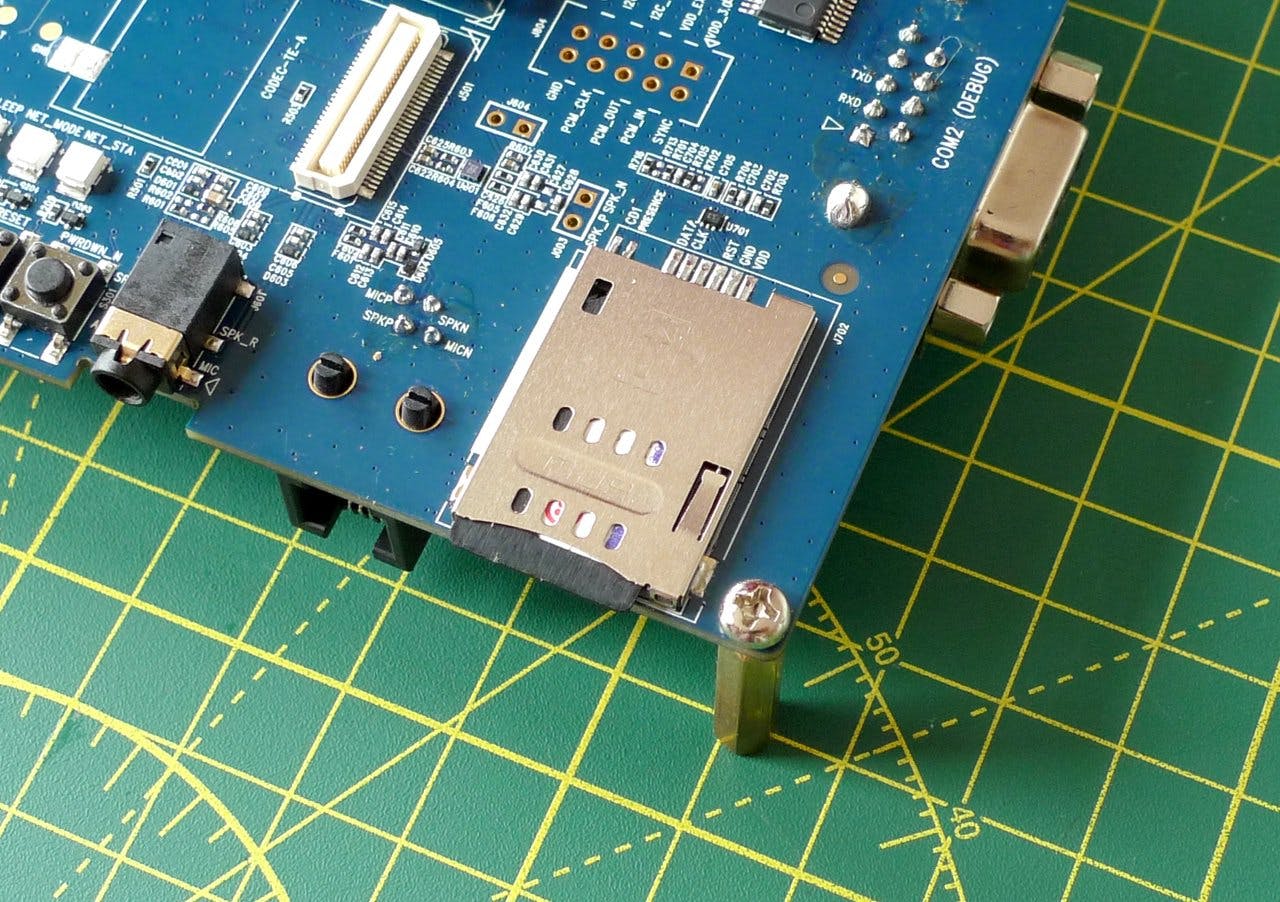
Slot a Super SIM into the board's SIM holder. It takes a standard mini-sized SIM, or a micro- or nano-SIM first fitted into an adapter:
-
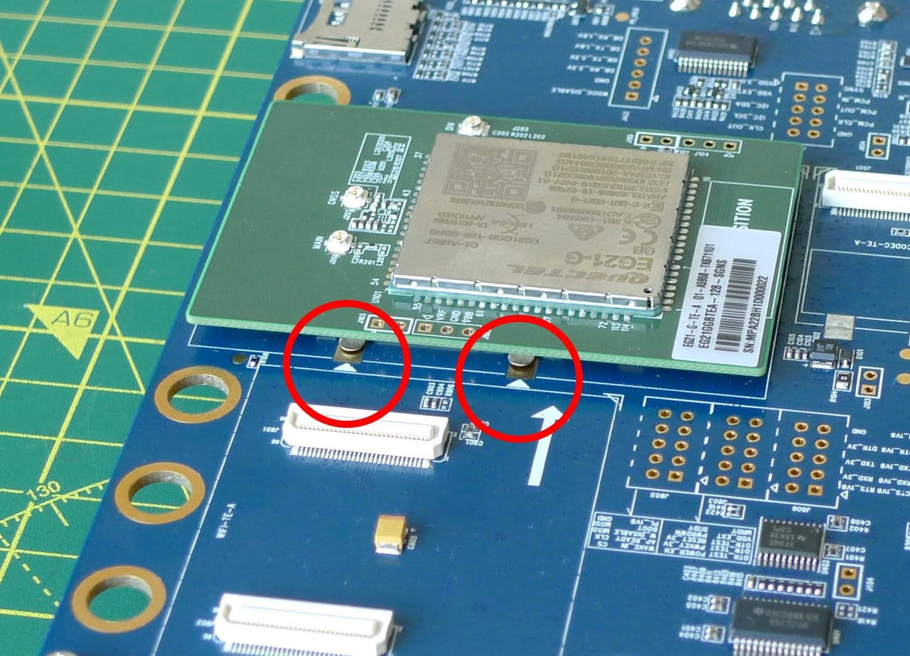
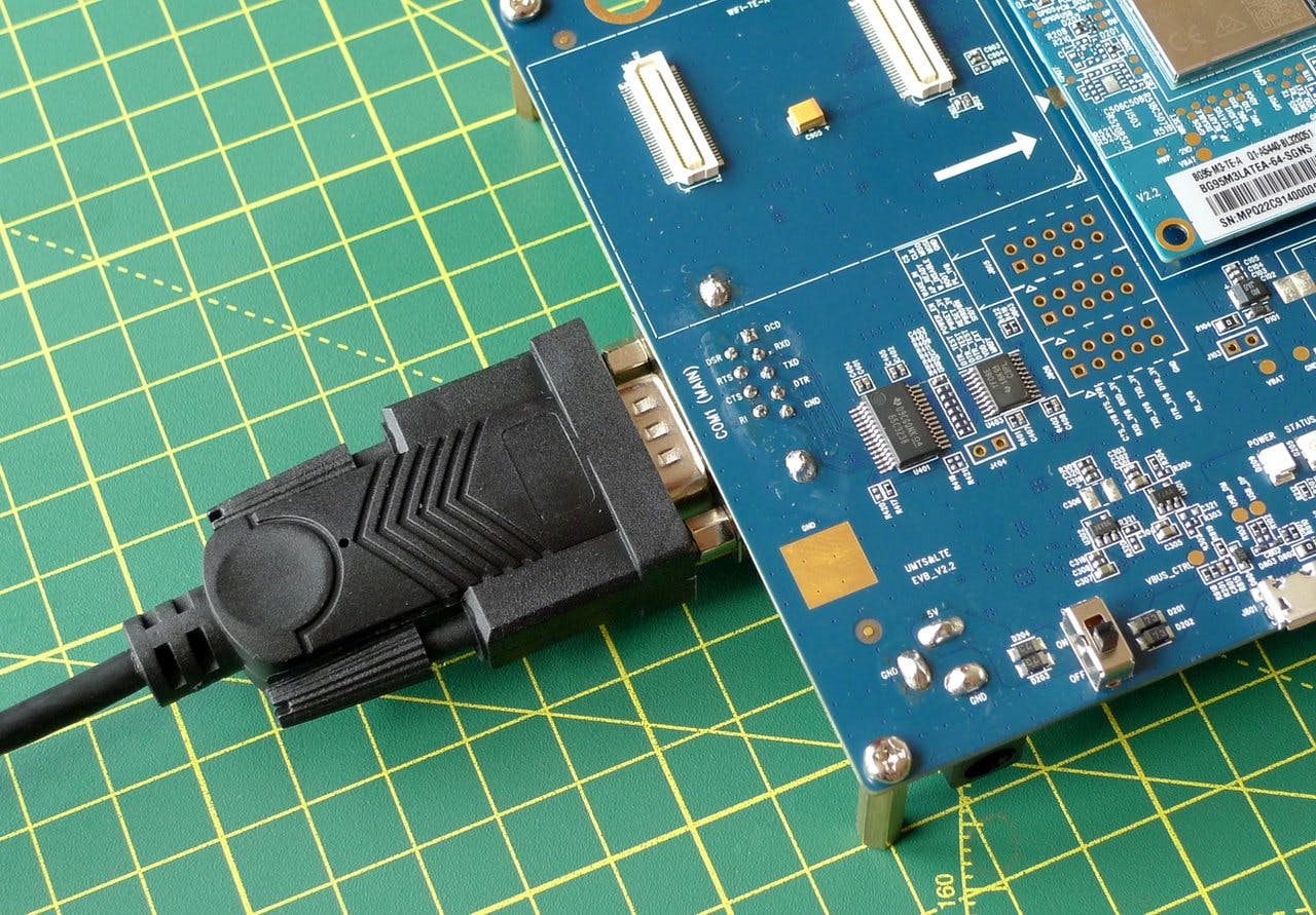
Fit the EG25-G test board to the top of the EVB, clipping it to the two connectors in the middle of the EVB. You can place it correctly by aligning the metal panel on the underside of the test board with the four arrows printed on the EVB:
-
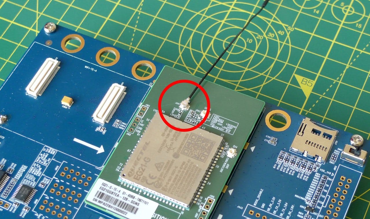
Connect one of the larger bundled antennas to the test board's uFL connector, marked MAIN. You will need one of the supplied whip adapters to join board and antenna:
-
Connect the EVB to your computer with the supplied RS232-USB cable. Connect the cable to the EVB's COM (MAIN) connector:
-
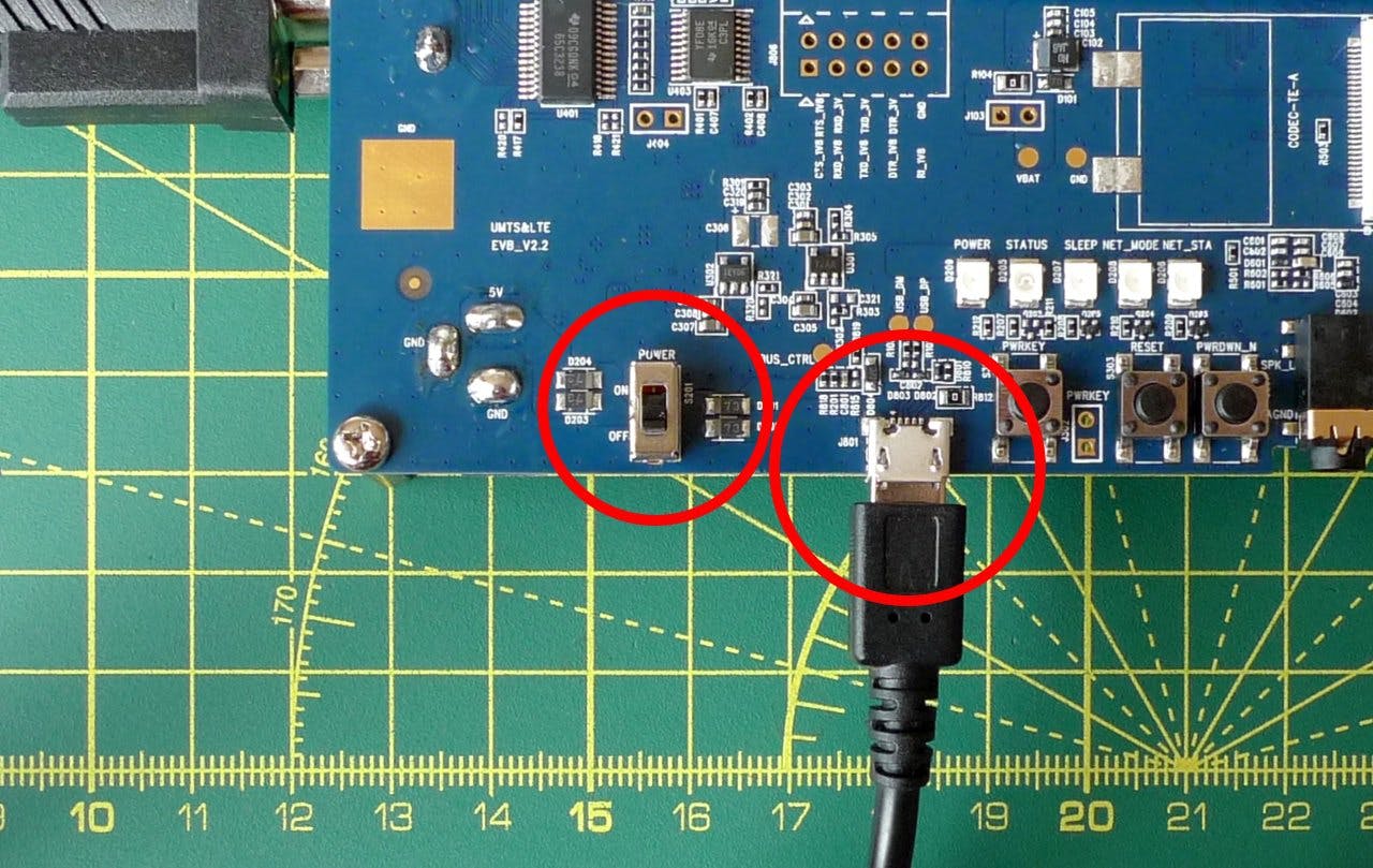
Connect the EVB to a suitable power source, such as a USB AC adapter, and then turn on the EVB by sliding the POWER switch to the position marked ON on the board:
-
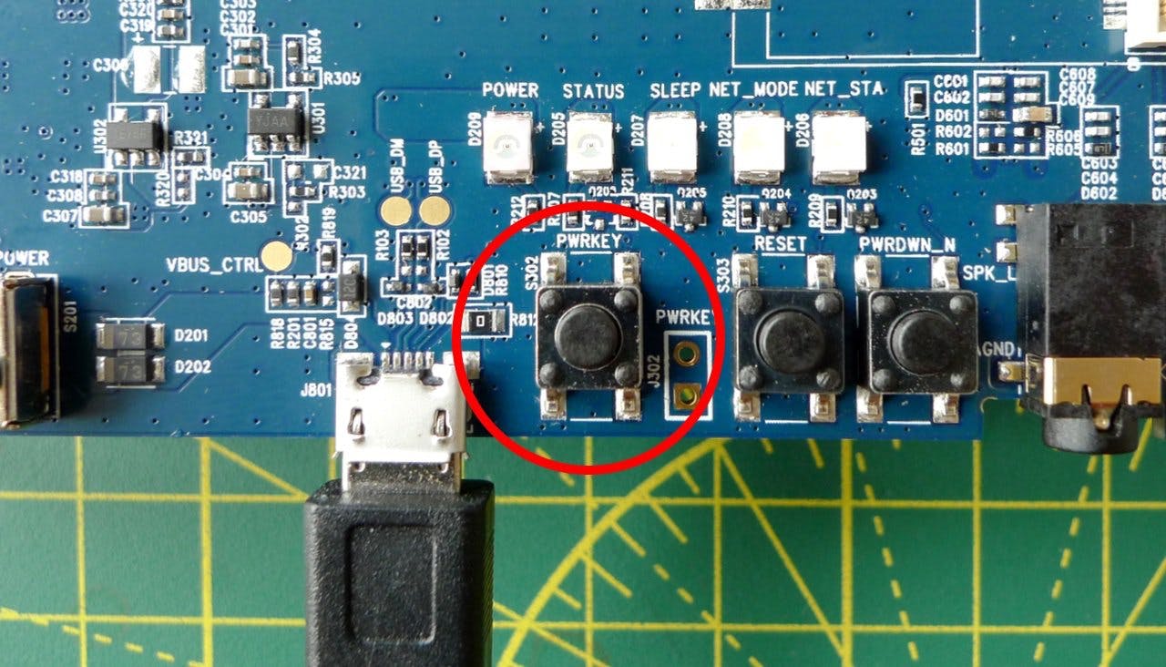
Press the PWRKEY button once to enable the modem test board:
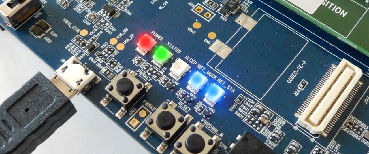
At this point the board's POWER, STATUS, and NET_MODE LEDs should be lit, and the NET_STA LED should be flashing:
- Open your distribution's terminal app.
-
Confirm connection with
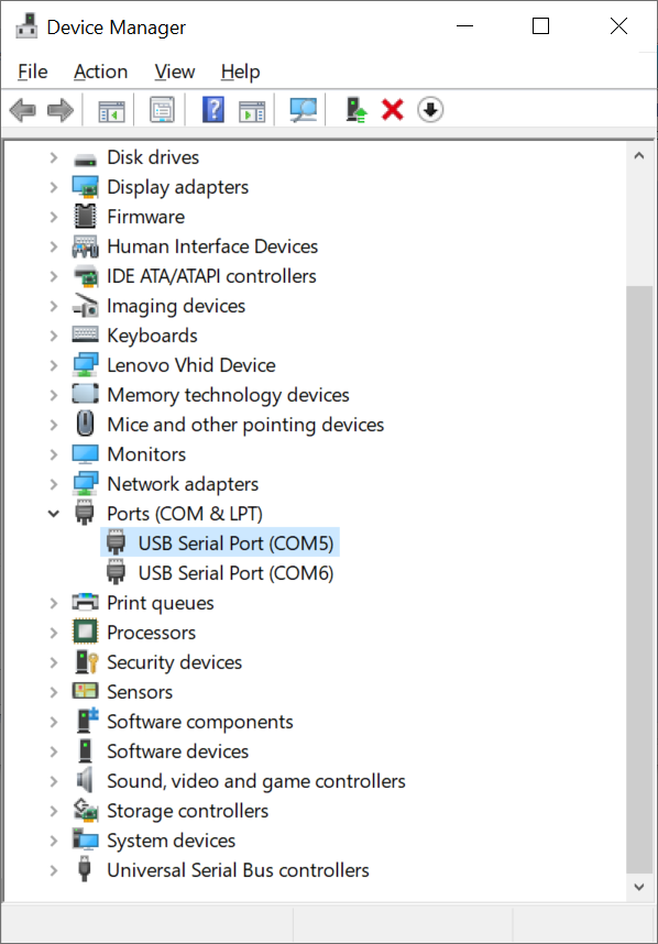
ls /dev/ttyUSB*— you should see a single device listed:/dev/ttyUSB0. This is the USB-to-serial device you'll use to communicate with the EVB. -
Using a serial tool like
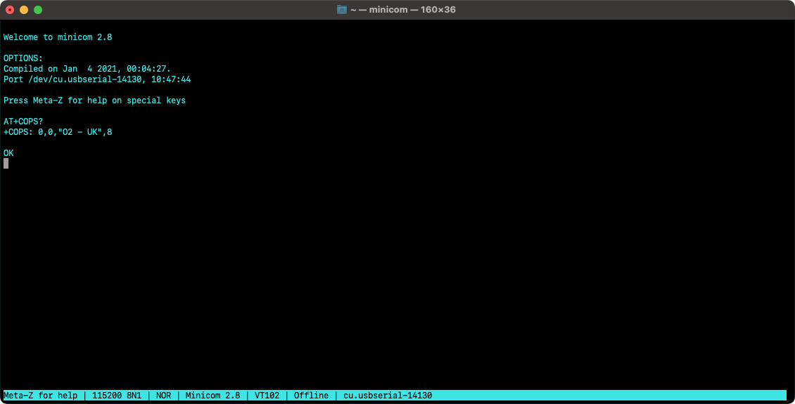
minicom— you will have to install this separately from source or a package manager likeapt— access the board withminicom -o -D /dev/ttyUSB0.
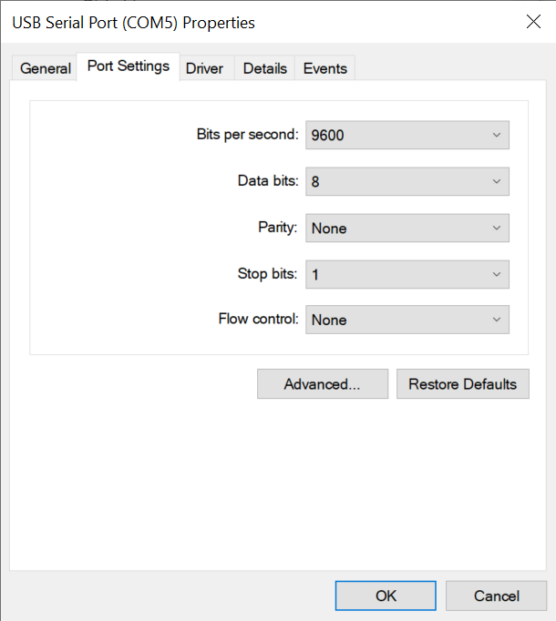
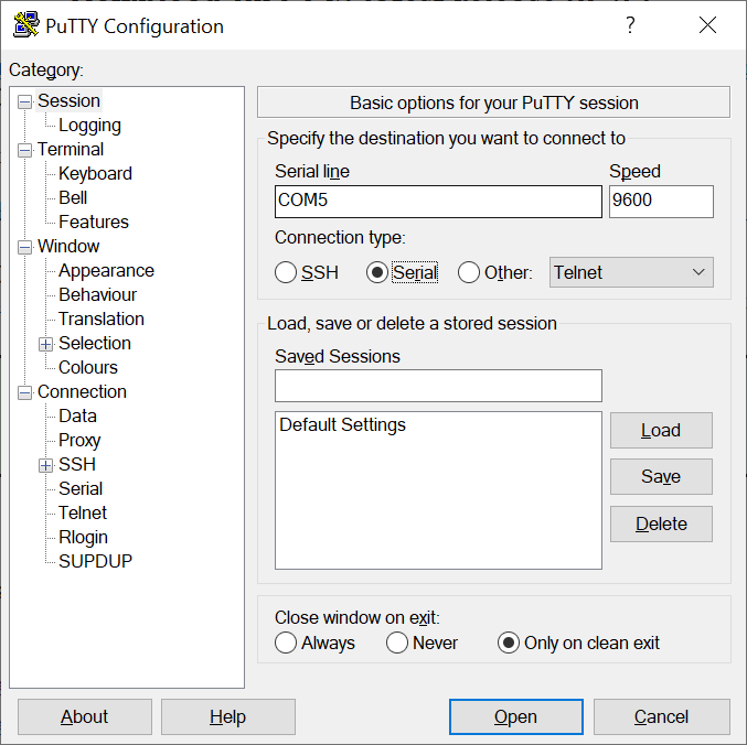
Within minicom or PuTTY, enter the AT command AT+COPS? to see which carrier your EG25-G is connected through:
The EG25-G supports LTE Cat-4 FDD in bands 1-5, 7-8, 12-13, 18-20, 25-26, 28, TDD in bands 38-41, and GSM at 850, 900, 1800, and 1900MHz.
If you wish to limit communications to LTE only, i.e., to disable 2G (GSM), issue this command:
_10AT+QCFG="nwscanmode",3
To instruct the modem to initiate data-centric attachments only — ie., not to make voice-oriented circuit-switched attachments too, which is the default — issue:
_10AT+QCFG="servicedomain",1
All these settings will be applied immediately.
Issue this AT command first to apply the Super SIM Access Point Name (APN):
_10AT+CGDCONT=1,"IP","super"
By default, the EG21-G will roam automatically, but you can force this by issuing:
_10AT+QCFG="roamservice",2
These settings will be applied immediately.
Having set the modem's APN, establish a Packet Data Protocol (PDP) context with the following command:
_10AT+QIACT=1
The single parameter is the PDP context's ID, in the range 1-16. It should match the first parameter in the above CGDCONT command.
You can also QIACT, in its read form, to get the device's data-connection state — and IP address, if the context is active:
_10AT+QIACT?_10+QIACT: 1,1,1,"100.74.24.186"
The first numeric parameter is the context ID. The second is its state — 1 indicates it is active — and the third is its type: 1 for IPV4 or 2 for IPV6.
Issue the Quectel-specific command
_10AT+QPING=1,"<TARGET_IP_ADDRESS_OR_NAME>"
to ping a server. Using one of Google's DNS servers as an example, this will yield:
_10+QPING: 0,"8.8.8.8",32,167,255_10+QPING: 0,"8.8.8.8",32,162,255_10+QPING: 0,"8.8.8.8",32,164,255_10+QPING: 0,"8.8.8.8",32,162,255_10+QPING: 0,4,4,0,162,167,163
To issue an HTTP GET request using the EG25-G's built-in HTTP client, run the following commands:
-
Set the PDP context ID:
AT+QHTTPCFG="contextid",1 -
Enable output of HTTP response headers:
AT+QHTTPCFG="responseheader",1 -
Activate the PDP context if it is not already active:
AT+QIACT=1 -
Set the target URL:
AT+QHTTPURL=21This sets the modem to receive, prompted by the outputCONNECT. The first parameter is the number of bytes the modem should expect to receive: it will end input after receiving this number of characters. The value of21comes from the URL below. The URL you provide must include the protocol, i.e.,http://. -
Upon receiving
CONNECT, enter the URL. For example:http://ifconfig.co/ip -
Make a
GETrequest:AT+QHTTPGET -
View the request:
AT+QHTTPREAD
The request will look like this:
_17HTTP/1.1 200 OK_17Date: Fri, 20 May 2022 08:52:56 GMT_17Content-Type: text/plain; charset=utf-8_17Content-Length: 13_17Connection: keep-alive_17CF-Cache-Status: DYNAMIC_17Report-To: {"endpoints":[{"url":"https:\/\/a.nel.cloudflare.com\/report\/v3?s=9fl%2B3t%2FRMhY2tMyWQDFAIM1mfFem0zLc7aONeXJ%2Fg4a%2FJPKFl%2BeGYElL5zwwuxi7%2BIfqx}_17NEL: {"success_fraction":0,"report_to":"cf-nel","max_age":604800}_17Server: cloudflare_17CF-RAY: 70e3d6ceb8cc5b17-IAD_17alt-svc: h3=":443"; ma=86400, h3-29=":443"; ma=86400_17_1744.204.32.40_17_17OK_17_17+QHTTPREAD: 0
Warning
This example uses a service that returns the IP address of the requester.
If you need to provide extra HTTP request headers, such Authorization: Basic <API_KEY>, or a custom header required by your server, issue
_10AT+QHTTPCFG="requestheader",1
to tell the modem to use the custom header that you will provide when you make each request. You will need to create a full HTTP request header separated from your request body by the characters <CR><LF>. Whether you make a POST or a GET request, include a byte-count parameter that totals the header plus the body (POST request) or header alone (GET request). For example, AT+QHTTPGET=60,512 for a 512-byte header (including the end-of-header <CR><LF>). The first parameter, 60, is a timeout. This usually defaults to 60 seconds but must be included if a second parameter is also present.
To issue a secure HTTP GET request using the EG21-G's built-in HTTP client, you follow the same procedure outlined above but with some extra steps included to configure SSL.
-
Set the PDP context ID:
AT+QHTTPCFG="contextid",1 -
Enable output of HTTP response headers:
AT+QHTTPCFG="responseheader",1 -
Activate the PDP context if it is not already active:
AT+QIACT=1 -
Select the SSL context ID for this PDP context ID:
AT+QHTTPCFG="sslctxid",1 -
Set the SSL version. Choose TLS 1.2:
AT+QSSLCFG="sslversion",1,3 -
Set the SSL cipher suite. Choose all types:
AT+QSSLCFG="ciphersuite",1,0xFFFF -
For testing, set the SSL verification level to 0, so no CA certificate is required:
AT+QSSLCFG="seclevel",0 -
Set the target URL:
AT+QHTTPURL=70This sets the modem to receive, prompted by the output CONNECT. The parameter is the number of bytes the modem should expect to receive: it will end input after receiving this number of characters. The value of70comes from the URL below. The URL you provide must include the protocol, i.e.,https://. -
Upon receiving
CONNECT, enter the URL. For example:https://twilio-cms-prod.s3.amazonaws.com/documents/super-sim-test.json -
Make a
GETrequest:AT+QHTTPGET -
View the response:
AT+QHTTPREAD
The request will look something like this:
_16HTTP/1.1 200 OK_16Date: Thu, 19 May 2022 10:23:25 GMT_16Last-Modified: Thu, 19 May 2022 10:05:25 GMT_16Accept-Ranges: bytes_16Content-Type: application/json_16Server: AmazonS3_16Content-Length: 128_16_16{_16 "userId": 1,_16 "id": 5,_16 "title": "laboriosam mollitia et enim quasi adipisci quia provident illum",_16 "completed": false }_16OK_16_16+QHTTPREAD: 0
Sending data from the modem to an Internet-hosted API follows the paths outlined above for the HTTP and HTTPS protocols. The key difference is that you call AT+QHTTPOST instead of AT+QHTTPGET.
Optionally, the QHTTPOST command takes a parameter indicating the amount of data you are sending. The modem uses this to read that number of bytes via the UART over which your application is communicating with it — just as it does with the QHTTPURL command we used earlier. If you are providing a custom HTTP request header, remember to include its length too.
While the EG21-G supports low-power modes for eDRX and PSM, support for these features will vary by visited network and location. The commands to enable each of these settings on the EG21-G are, respectively:
_10AT+CEDRXS=1_10AT+CPSMS=1
Both settings, but especially PSM, can prevent the modem from being accessible through the terminal during its sleep time. It's best to experiment with these features with the modem local. To disable all power saving if needed, send:
_10AT+CEDRXS=0_10AT+CPSMS=0
Keen to find out more about how the Quectel EG25-G cellular module can power your IoT product design? Contact Quectel sales to line up a conversation.
And don't forget, we're always ready to discuss how Super SIM can help you too.
- EG25-G Data Sheet
- EG25-G AT Commands Manual Quectel login required
- EG25-G GNSS Application Note