Microvisor Nucleo Development Board
The Microvisor Nucleo Development Board (NDB) is a complete evaluation and development platform for Microvisor and the STM32U585 microcontroller.
The board breaks out all of the user-accessible STM32U585 GPIO pins and peripherals into two rows of 0.1-inch pins in the standard ST Nucleo layout. It also features an LED for user feedback.

The NDB supports cellular connectivity powered by KORE Wireless Super SIM: the board design includes a Mini PCIe slot and surface-mount full coax antenna to allow you to add any supported cellular module card.
The NDB provides other networking options: a PHY and RJ-45 connector to connect the board to Ethernet networks, and traces for an Espressif ESP32-WROOM-32E WiFi module. Personal area networking is supported through the Espressif ESP32-WROOM-32E's BLE functionality.
Crucially, the NDB design will show you how to integrate key Microvisor components and features into your own Microvisor-empowered IoT product design. We recommend that all designers of these products start out by reviewing the NDB schematics.
Warning
Not all of the functionality made available by the board's hardware has yet been enabled in Microvisor.

- GPIO header.
- SMT antenna.
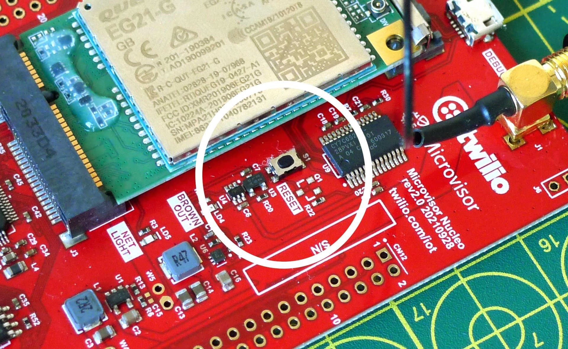
- Reset button.
- Network activity LED.
- Power brownout LED.
- Application-controllable LED.
- STM32U585 with Microvisor.
- Quectel EG21-G global cellular modem.
- USB-C power input.
- System LED.
- Super SIM.
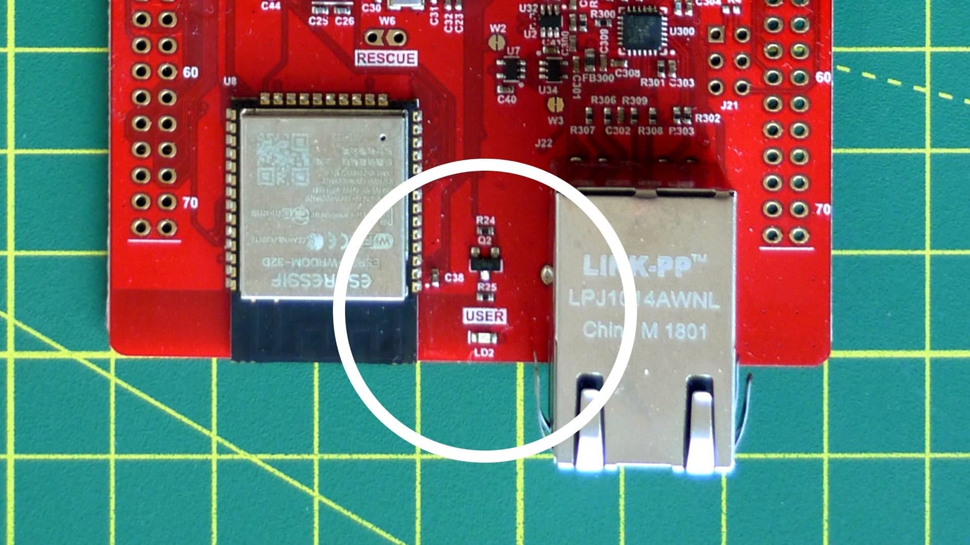
- ESP32 WiFi/BLE module.
- RJ-45 Ethernet jack.
The NDB features a USB-C port for convenient power input.
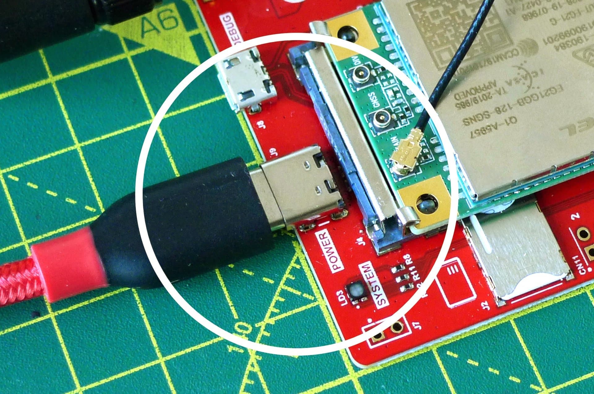
It does not support the connection of rechargeable cells.
The board features a low-power indicator LED, marked BROWNOUT (LD4). It will light when the modem draws more power than the board's supply can provide.
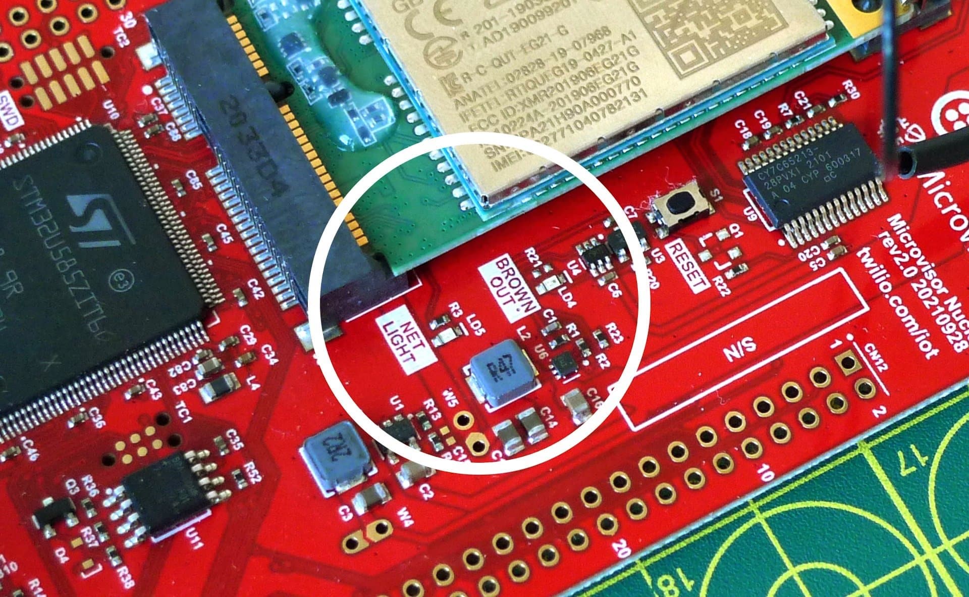
The brownout indicator may also light if you are powering the board with an AC adapter or USB-C port that is not able to deliver sufficient power. Make sure your adapter delivers at least 15W (5V at 3A), and check for cable damage.
The BROWNOUT LED will be cleared when the board is reset, either in code or manually.
Warning
With the current revision of the board, the BROWNOUT LED will be lit even if the power draw is under 15W. This is a known issue and will be addressed in a coming board design update.

The board's MCU is the ST Microelectronics STM32U585. This version of the STM32U5 comes pre-loaded with Microvisor, but in most other respects operates exactly like the standard STM32U5 and offers the same peripherals and pin functionality. However, some STM32U585 components are managed by Microvisor and are therefore not directly available to application code:
RCC— the STM32U585's reset and clock controller.RNG— the STM32U585's true random-number generator, used to make secure TLS network connections and for other security functions.RTC— the STM32U585's real-time clock. Microvisor owns the RTC, because it has to control when and whether the STM32U585 enters the deep-sleep Standby mode.PWR— the STM32U585's power controller.OCTOSPI1— the STM32U585's interface to the external QSPI, used to securely store upgrade Bundles.OTG_FS— the STM32U585's USB controller, used to connect to the cellular modem.UART5— one of the STM32U585's UART peripherals, used to connect to the cellular modem.SDMMC1— the STM32U585's Secure Digital IO, use to connect to the WiFi+BLE module.
For details on how to work with these limitations, please see Develop IoT Applications for Microvisor
The NDB incorporates a M2 (Mini PCIe) connector into which you can slot a cellular module. Microvisor initially supports the Quectel EG21-G LTE Cat 1 cellular module for mobile connections to the Internet. Microvisor will reserve this module's networking functionality, and the application must establish cellular Internet communications via Microvisor system calls.
The application will have full access to the EG21-G for GNSS (GPS, GLONASS, BeiDou/Compass, Galileo, and QZSS) operations, but this is not expected to be ready during the Microvisor Beta Program.
In addition to the modem, you will need to add a Super SIM in Nano card format.
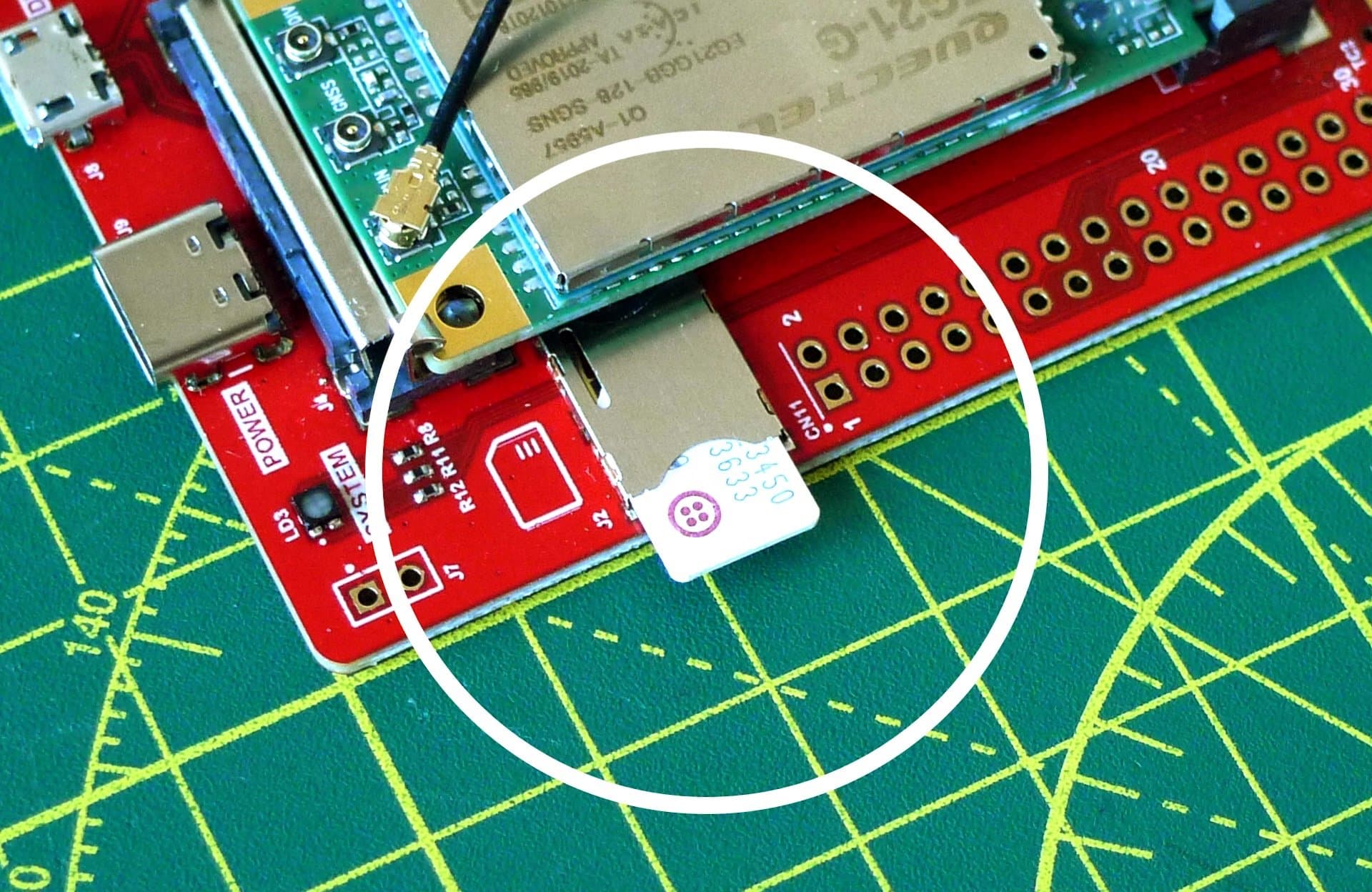
The board silkscreen indicates the correct orientation of the SIM card.
This is the cellular modem's network activity indicator (LD5).
With a Quectel EG21-G MIni PCIe card installed, this will blink slowly while the device is idling (long blink) or searching for the network (short blink), and blink rapidly during data transfer.
The NDB incorporates an Espressif ESP32-WROOM-32E WiFi+BLE module as a communications co-processor for WLAN connections to the Internet. If this module is the device's primary route to the Internet, Microvisor will reserve its WiFi functionality, and the application must establish WLAN Internet communications via Microvisor system calls. The ESP32 firmware and stack is provided by Microvisor.
The application will have full access to the ESP32 for BLE operations, via system calls, but this is not expected to be available during the Microvisor Beta Programs.
The application will also have full access to the WiFi subsystem for local networking.
Microvisor 0.4.x enables the use of WiFi as an alternative to cellular for a device's primary Internet connection.
The NDB incorporates a Bel Stewart SI-50170-F Ethernet RJ-45 connector linked to the Espressif ESP32-WROOM-32E module via a Microchip LAN8720A PHY. If this is to be the device's primary route to the Internet, Microvisor will reserve its Ethernet functionality, and the application must establish Internet communications via Microvisor system calls. The ESP32 firmware and stack is provided by Microvisor, so your application does not need to incorporate them itself.
The application will also have full access to the Ethernet subsystem for local networking.
Microvisor 0.4.x enables the use of WiFi as an alternative to cellular for a device's primary Internet connection.
The Quectel cellular module also supports GNSS (Global Navigation Satellite System) operation using all of the major satellite-based location detection systems, including GPS, Galileo, Glonass, and BDS. It will need to be connected to an external antenna for GNSS operation — most M2 board designs incorporates a u.FL connector to which a suitable GNSS antenna can be connected.
GNSS support is not expected to be available during the Microvisor Pilot or Beta Programs.
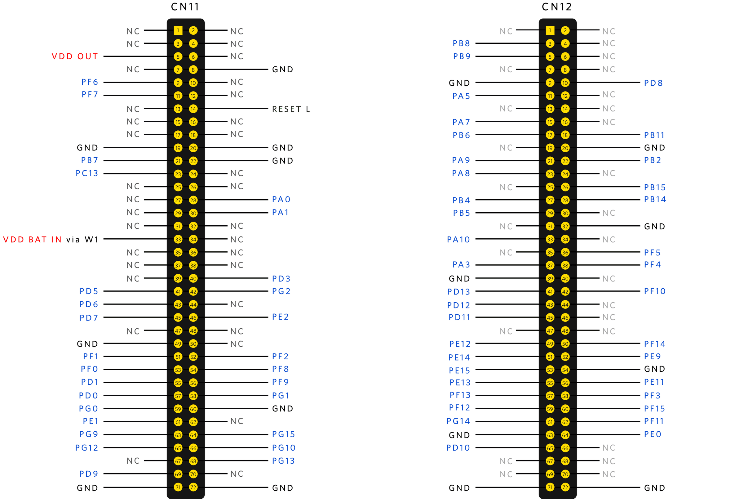
All of the STM32U585's GPIO pins that are available to the user are broken out through the NDB's two female header blocks, marked CN11 and CN12. Any pins not present are reserved for Microvisor's use both on this board and on customer implementations. Please see the STM32U585 data sheet for the functionality enabled at each pin. The headers are connected as follows:
The NDB incorporates a cellular modem, an ESP32 WiFi/BLE module, and an Ethernet jack. Any of these features may be used by the NDB to connect to the Internet. This takes place automatically at power on:
- For Ethernet, connect an RJ-45 cable between your NDB and your router, then connect the NDB to power.
- For WiFi, add your wireless network's credentials to the board (see below) and then power-cycle the NDB.
- For cellular, ensure a Super SIM has been fitted into the SIM slot.
When it is re-booted, Microvisor will attempt to connect to the Internet in this order:
- With Ethernet if it is wired up to an active network.
- With WiFi if it is configured with credentials and the specified network can be found.
- Cellular via Super SIM.
As soon as a connection is made, no other devices are used. For example, if Ethernet is not connected, Microvisor will attempt to connect by WiFi. If it succeeds, it will not attempt to connect by cellular.
To configure your NDB's WiFi credentials, follow these steps:
-
Download
miniterm.pyfrom the PySerial GitHub repo and save it on your computer. -
Connect the supplied Micro-USB cable to your computer and to the NDB's CONTROL port. If you use your own Micro USB cable, make sure it is data-capable, not power only.
-
Run
python3 miniterm.py /dev/ttyUSB0 115200. -
Press RESET on the NDB.

-
The NDB's SYSTEM LED will turn solid blue, and no application code will be run. On your computer, you'll see
Provisioning UART enabledinminiterm. If the LED does not turn blue, you may be using a power-only Micro USB cable. -
Enter
wifi setConfig <YOUR_SSID> <YOUR_PASSWORD>:
-
You can check you entered your credentials correctly by entering
wifi getConfig. -
Hit
Ctrl-]to exitminiterm. -
Remove the Micro-USB cable from the NDB and power-cycle the board. At this time, a full power-cycle is required: pressing RESET will not move the board out of provisioning mode.
Microvisor signals system status on the three-color LED marked SYSTEM (LD3).
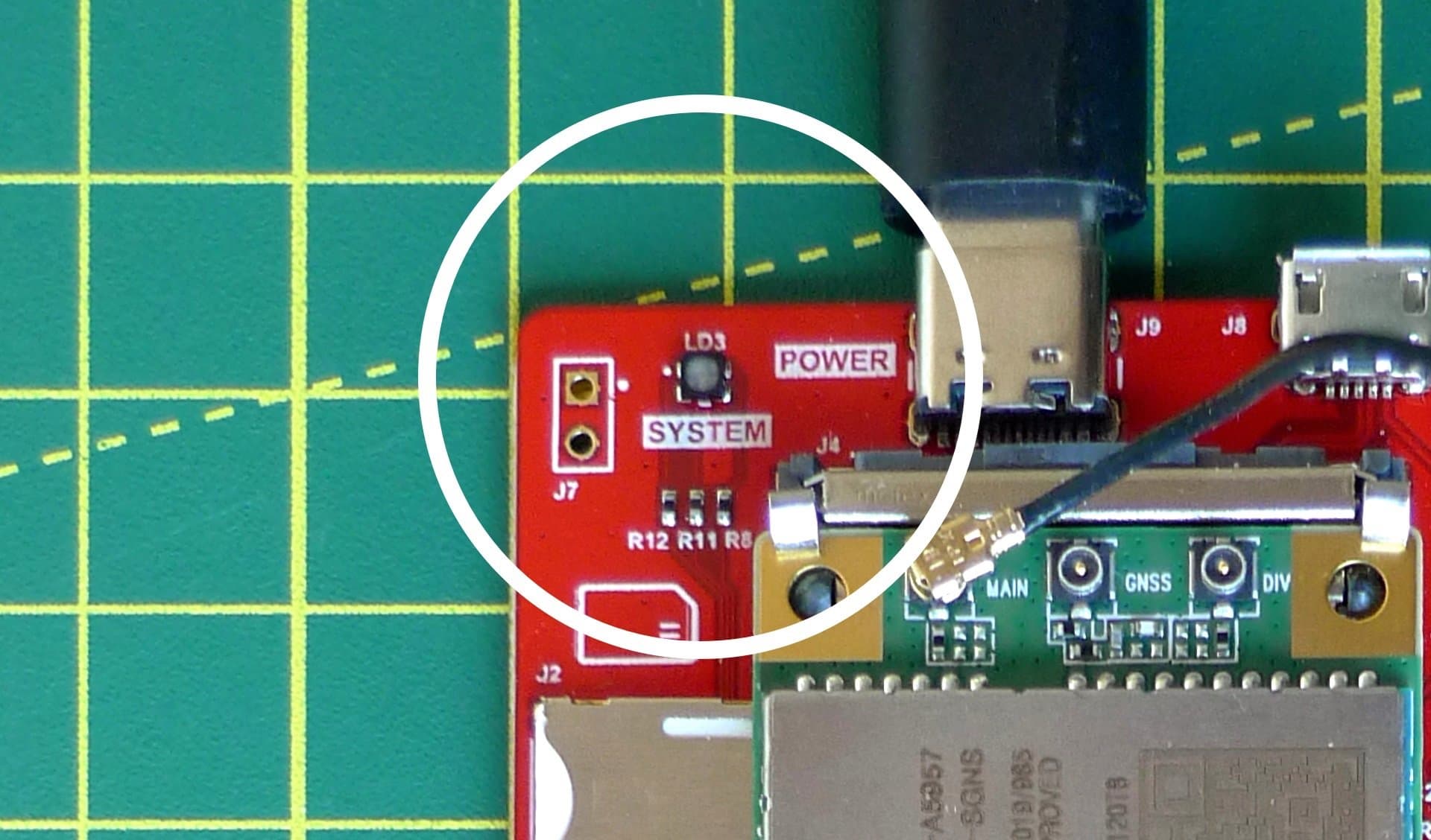
System states are presented as sequences of colors. The LED blinks in some sequences and is solid in others. A list of status patterns can be found here.
You should check this LED for error or success conditions, i.e., a pattern being displayed repeatedly without change. Do not use it to track transient states.
The LED marked USER (LD2) is connected to the STM32U585's GPIO pin PA5. Set this pin high to turn on the LED.
You can manually trigger a device reboot at any time by pushing the RESET button.
The Micro USB port marked DEBUG or CONTROL, depending on board revision, is currently disabled and is reserved for future use.
134 x 70 x 15mm59g (without antenna) 76g (with antenna)
- Update Nano SIM socket footprint.
- U4 change to SOT23-6 for better availability.
- U4 MR is optionally connected to PF15, by default LD4 unpowered and U4 in reset.
- TC1 change to standard Jlink.
- SWD connector available as tag connect as well as 50mil header.
- No Electrical changes; cosmetic changes only.
- Prototype.
- Board schematic (PDF)
- Gerber (ZIP)
- Altium (ZIP)
- Bill of Materials (BoM) (XLS)
- Bel Stewart SI-50170-F Ethernet Jack
- Espressif ESP32-WROOM-32E data sheet (PDF)
- Microchip LAN8720A PHY data sheet (PDF)
- Quectel EG21-G Mini-PCIe Card
- STMicroelectronics STM32U585 data sheet (PDF)
Microvisor Help and Support
We welcome all inquiries you may have about Microvisor and its implementation, and any support questions that arise once you've begun developing with Microvisor. Please submit your queries via a KORE Wireless ticket: log in to the Kore console and click the Contact Support button in the left-hand navbar.