Disconnected Device Debugging with Microvisor
Battery operated devices commonly disable wireless and cellular networks to save power. Mains-powered devices may be configured to continue operating even when connectivity has been lost due to circumstances beyond the device's control. With no network connectivity, logging is a challenge.
In order to add visibility to the state of your product during periods of unexpected connectivity loss, you can employ one of the many digital communication protocols available to your device's microcontroller, in particular UART. This standard bus is a great choice for its ease of use and wide availability.
By using a UART for offline debugging you can send the same messages you would via Microvisor's mvServerLog() system call to a serial port with just a few hardware modifications. We'll describe below how you can take advantage of this technique.
You'll need a few extra tools in order to use UART for debugging. These tools comprise both software and hardware but are either low cost or free.
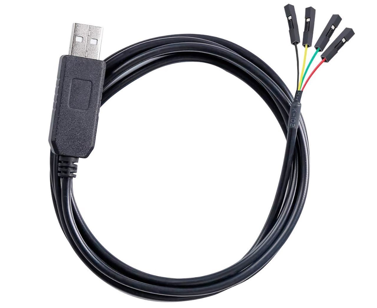
We recommend using a TTL UART-to-USB (COM port emulator) cable to view debug messages on your workstation. Connect this cable to pins (or test points) on the DUT.
You will also need terminal software and to modify the device code to output debug messages over serial. We have collected the information you need to source components and software.
We recommend FTDI cables because they are highly available and relatively inexpensive. They are available with either a female 0.1-inch socket or bare wire termination, so select one on the basis of your application. They are available in 3.3V and 5V signal levels, and it is important that you always use the version that matches your microcontroller's GPIO logic high voltage.
You will need to install the FTDI drivers for your OS. Ubuntu 20.0.4 comes with FTDI drivers built in, as does macOS (10.9 and above). Windows users will need to install VCP (Virtual COM Port) drivers, which are available from FTDI.
There are many options available depending on your OS. Linux and macOS both come with Terminal utilities; these can be used to run a command-line utility called Minicom which lets you send and receive information via UART. Install Minicom using your OS' package manager.
- Linux
sudo apt install minicom - macOS
brew install minicom
Windows users should download Simon Tatham's PuTTY, which combines the role of terminal and Minicom.
Info
Minicom installation on macOS requires the Homebrew package manager. Install it from its website if you have not done so already.
To demonstrate UART connectivity, we'll use the Microvisor Nucleo Development Board (NDB). Microvisor makes four full-power UART buses — USART1, USART2, USART3, and UART4 — available to the application. We will use USART2 in the code below, but you should choose your own bus based on your device's pin availability.
USART2 connects through GPIO pins PA2 and PD5 (TX), and PA3 and PD6 (RX). For the sample code, we've chosen pins PD5 and PD6. In fact, we only need PD5, as we'll configure the UART for TX only.
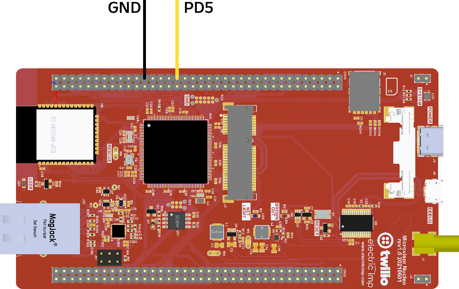
Connect your FTDI cable to one of your computer's USB ports, and its RX wire (usually colored yellow) to PD5, which is pin 41 of block CN11 on the NDB. This is the GPIO header alongside the SIM card slot. Connect the FTDI's GND wire to pin 49 of CN11.
Be sure to set the serial terminal connection to use the FTDI cable and match the following settings:
- Baud Rate User choice, e.g., 115,200
- Data Bits/Word Length 8
- Parity None
- Stop Bits 1
On your computer:
Open a terminal. The device file should be /dev/ttyACM0. You may need to ensure you have access to the serial port: on most distributions this can be done by adding your user account to the dialout user group.
Run minicom -o -D /dev/ttyACM0
The following sample can be used to add serial logging to your application. It leverages USART2 via pin PD5. The bus is set to TX only and an '8N1' configuration. You can alter these choices by editing the functions UART_init() and HAL_UART_MspInit(). In fact, the code demonstrates how to set up a standard UART connection using the STM32U585 HAL library: configure the UART, set the appropriate clocks, and configure the GPIO pins supporting the bus.
In your project, create the files uart_logging.h and uart_logging.c, and add the following code to the latter:
1#include "uart_logging.h"23UART_HandleTypeDef uart;45/**6* @brief Configure STM32U585 UART1.7*/8void UART_init() {9uart.Instance = USART2;10uart.Init.BaudRate = 115200; // Match your chosen speed11uart.Init.WordLength = UART_WORDLENGTH_8B; // 812uart.Init.StopBits = UART_STOPBITS_1; // N13uart.Init.Parity = UART_PARITY_NONE; // 114uart.Init.Mode = UART_MODE_TX; // TX only mode15uart.Init.HwFlowCtl = UART_HWCONTROL_NONE; // No CTS/RTS1617// Initialize the UART18if (HAL_UART_Init(&uart) != HAL_OK) {19// Log error20return;21}22}2324/**25* @brief HAL-called function to configure UART.26*27* @param uart: A HAL UART_HandleTypeDef pointer to the UART instance.28*/29void HAL_UART_MspInit(UART_HandleTypeDef *uart) {30// This SDK-named function is called by HAL_UART_Init()3132// Configure U5 peripheral clock33RCC_PeriphCLKInitTypeDef PeriphClkInit = { 0 };34PeriphClkInit.PeriphClockSelection = RCC_PERIPHCLK_USART2;35PeriphClkInit.Usart2ClockSelection = RCC_USART2CLKSOURCE_PCLK1;3637// Initialize U5 peripheral clock38if (HAL_RCCEx_PeriphCLKConfig(&PeriphClkInit) != HAL_OK) {39// Log error40return;41}4243// Enable the UART GPIO interface clock44__HAL_RCC_GPIOD_CLK_ENABLE();4546// Configure the GPIO pins for UART47// Pin PD5 - TX48GPIO_InitTypeDef gpioConfig = { 0 };49gpioConfig.Pin = GPIO_PIN_5; // TX pin50gpioConfig.Mode = GPIO_MODE_AF_PP; // Pin's alt function with pull...51gpioConfig.Pull = GPIO_NOPULL; // ...but don't apply a pull52gpioConfig.Speed = GPIO_SPEED_FREQ_HIGH;53gpioConfig.Alternate = GPIO_AF7_USART2; // Select the alt function5455// Initialize the pins with the setup data56HAL_GPIO_Init(GPIOD, &gpioConfig);5758// Enable the UART clock59__HAL_RCC_USART2_CLK_ENABLE();60}6162/**63* @brief Issue any log message via serial logging.64*65* @param format_string Message string with optional formatting66* @param ... Arbitrary number of additional args67*/68void uartlog(char* format_string, ...) {69char buffer[1024] = {0};70va_list args;71va_start(args, format_string);7273// Add a timestamp74char timestamp[64] = {0};75uint64_t usec = 0;76time_t sec = 0;77time_t msec = 0;78enum MvStatus status = mvGetWallTime(&usec);79if (status == MV_STATUS_OKAY) {80// Get the second and millisecond times81sec = (time_t)usec / 1000000;82msec = (time_t)usec / 1000;83}8485// Write time string as "2022-05-10 13:30:58.XXX "86strftime(timestamp, 64, "%F %T.XXX ", gmtime(&sec));8788// Insert the millisecond time over the XXX89sprintf(×tamp[20], "%03u ", (unsigned)(msec % 1000));9091// Write the timestamp to the message92strcpy(buffer, timestamp);93size_t len = strlen(timestamp);9495// Write the formatted text to the message96vsnprintf(&buffer[len], 1016, format_string, args);9798// Add RETURN and NEWLINE to the message and output to UART99sprintf(&buffer[strlen(buffer)], "\r\n");100HAL_UART_Transmit(&uart,101(const uint8_t*)buffer,102(uint16_t)strlen(buffer),103100);104va_end(args);105}
Add a declaration for the first and last function to the header file:
1void UART_init();2void uartlog(bool is_err, char* format_string, ...);
Make sure the files are included in your project's build configuration, and that you call UART_init() from your main(). Build and deploy a new version of your application.
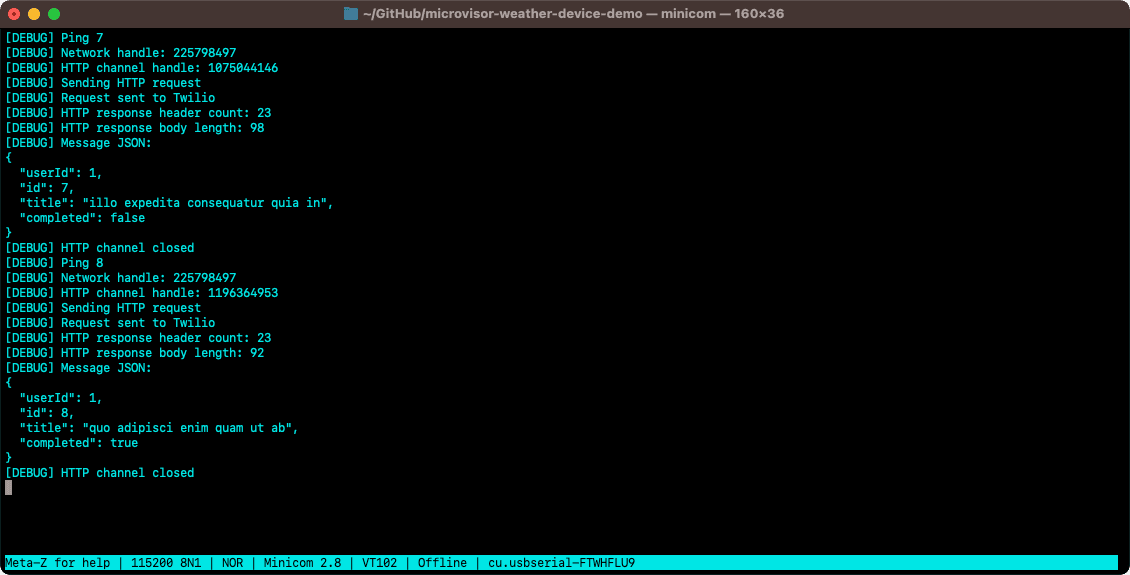
Now update your code to call uartlog() alongside mvServerLog(). The function takes a format string and zero or more arguments to be interpolated into it. The message passed into the call will be UTC-timestamped and issued using Microvisor application logging and over UART. If the device is connected, you can view both streams in parallel, or you can view solely the UART output if the device is disconnected.
Microvisor Help and Support
We welcome all inquiries you may have about Microvisor and its implementation, and any support questions that arise once you've begun developing with Microvisor. Please submit your queries via a KORE Wireless ticket: log in to the Kore console and click the Contact Support button in the left-hand navbar.