Garduino Phone – Saving Plants from Negligent Parents using Twilio, Arduino and Sinatra
Time to read:
June 17, 2014
Written by

A few months back I built some raised beds with the intention of giving my wife and I something to do on the weekends. However two things happened immediately after I built the beds that really hindered my gardening ambitions. First, the garden went totally insane sprouting up 4 foot brussel sprouts, producing more fat beets than Ryan Lewis and in general taking over our whole backyard. Second and more importantly, we had our first child. Needless to say the garden quickly became neglected. Our rock-hard broccoli florets and orange wilting lettuce were obviously under-watered plants. I was letting my garden down even though my friends took to calling me “Farmer Jarod.” It was time to hack this garden and show my plants some love.
The Garduino Phone
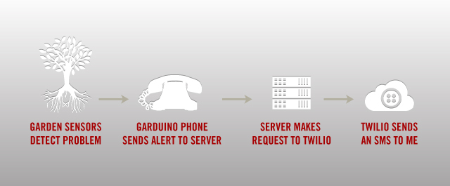
My first approach was to scour the internet for an out-of-the-box tutorial. However, I found that most of the solutions out there were either too basic (one sensor/one-way communication), or way over the top (massive clusters of micro-controllers). In the end I wanted a little brain in my garden that would alert me when things got out of hand, as well as respond to my inquiries when I’m out of town and need to check the health of things. So I decided to build this little “Garduino Phone” and put it inside of an old rotary telephone that I bought for $3 at a yard sale.
Here’s what you need to understand before you build a garden monitor. In San Diego we get frosty nights and blistering summer days which can kill my cold crops (brussel sprouts, cabbage, etc). Even warm crops like corn and onion don’t like soil that ever gets above 90 degrees, and this is a real possibility in San Diego. So our garden needed to have a moisture sensor and a thermo sensor, but if you are building this for indoor use you could probably skip the thermo sensor. Also if you are building an indoor garden you should check out this post on a self-watering plant using Arduino.
Step 1: Setup
- Arduino Uno
- Arduino WiFi Shield
- Moisture Sensor
- Thermo Sensor
- 7 Jumper Cables (male to male)
- Waterproof case (2-liter bottle, old telephone, seal blubber, whatever)
- 4.7k resistor (purple, red, yellow, gold)
- Power supply
- Breadboard
Prepare Your System
- Download and install the Arduino IDE from http://arduino.cc/en/Main/Software.
- Grab the code from github https://github.com/jarodreyes/garden-phone/
- Install the ngrok utility from https://ngrok.com/download
- Signup for a free Pusher account http://pusher.com/pricing
Signup for Twilio
Go to twilio.com/try-twilio and sign up for your free number. As good measure whenever I buy a new phone number I immediately add it to my ENV variables.
Step 2: The Circuit
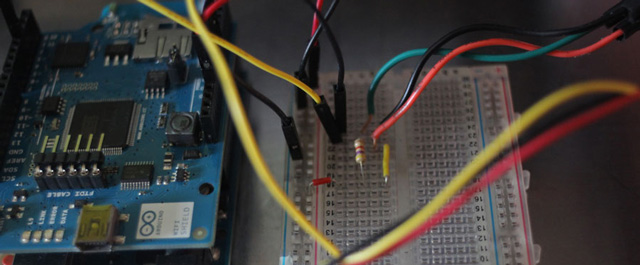
Setting up the circuit should be simple but I found some gotchas that I’ll be pointing out along the way so that you don’t get stuck. We have two sensors, one in a digital pin and the other in an Analog pin. The only real trickery we do here is add a 4.7k pull-up resistor in order to use the 1-wire bus. Here is the circuit in completion.
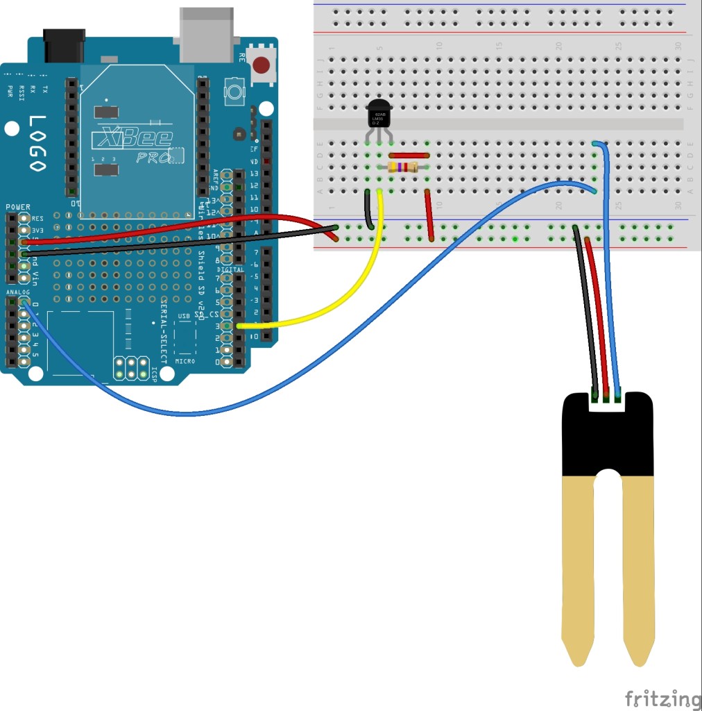
Instructions:
1. Plug WiFi shield into Arduino Uno
2. Jumper from 5V to (+) on breadboard
3. Jumper from GND to (-) on breadboard
4. Plug in moisture sensor to (-) (+) and A0 on Arduino
5. Thermo sensor (blue/green) wire to Digital Pin 3
6. Thermo sensor (white/yellow) wire to […check diagram]
7. 4.7k resistor from the green wire to power
Step 3: Server Code
I chose to use Sinatra as our Server. Sinatra allows us to write a simple one-page Ruby file that runs the whole shebang. In this case our server only needs to do three things:
Receive data from the arduino
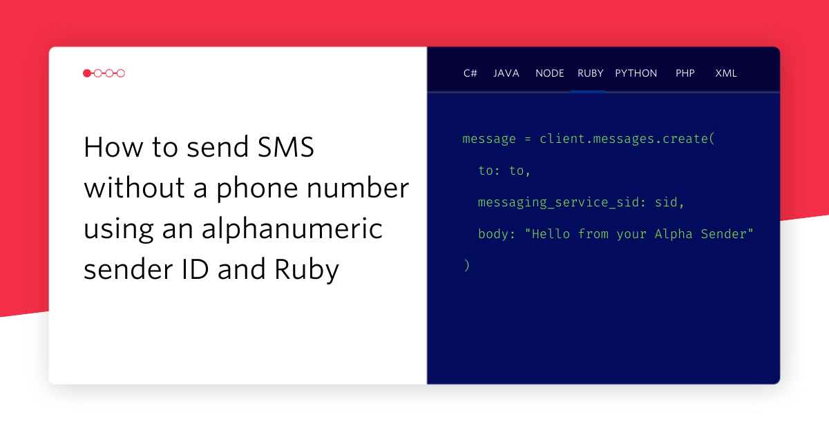
Send an SMS to a phone
Receive SMS from my phone, send data from Arduino in return (using Pusher and Twilio APIs)
First let’s setup our Sinatra file with all of the requirements. Github ➭
We setup our app with requirements, initiate the APIs with their tokens and define some global variables. Next let’s setup our endpoint that will listen for arduino data. Github ➭
This function grabs the parameters from the GET request, checks if it’s an alert and then sends the SMS. The reason we are checking if this is an alert is because the Arduino is capable of initiating this request when it sees abnormal sensor data, in which case it will pass an alert parameter which acts as a warning message (eg: “Too Hot!”; “Low Water!”)
Lastly let’s setup our endpoint for Twilio. Github ➭
We’ll talk more about this little guy later, but for now just know that it serves up the URL we are going to give Twilio.
Now we just need to host this Sinatra app so that our Arduino has somewhere to post it’s data. Luckily Ngrok makes this incredibly easy.
Hosting with Ngrok
In a new terminal window run your Sinatra app using rackup:
Now you should have a Ruby instance running on port 9292. So in order to make this a public url simply run ./nrgok 9292 from the directory you installed it.
Now let’s add this URL to Twilio. Once you’ve logged in to Twilio, click on numbers and choose the number for your garden monitor and you should see the following screen:
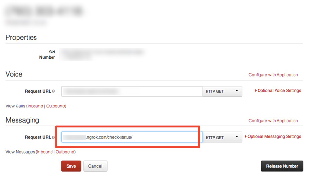
Enter the Ngrok url into the Messaging url field and you’re done! Now that we have a public endpoint let’s setup the Arduino.
Step 4: Arduino Code
When I struck out on this project I was slightly daunted by the lack of consensus and documentation about using web sockets to interact with an Arduino. However, it turns out the most straightforward approach is to use the Arduino’s WiFi client to initiate HTTP requests.
The sketch I included in the github repo contains a few lines of code that initiates a Pusher connection and receive an inbound command, but since this process has been thoroughly covered in my Halloween Arduino post I will skip it. If you would like more information on how to enable your Arduino to accept commands using the Pusher library read my Halloween post. Now let’s talk about the code.
The Arduino code needs to do the following things:
- Connect to the wireless access point (WPA in this example)
- Assign the two sensor inputs and register the sensors
- Get sensor readings
- Send an alert to my server when the sensors detect dangerous levels
Before we write the code you need to go grab these libraries and install them in your Arduino libraries folder:
- ArduinoPusherLibrary – Allows the Arduino to communicate with the Pusher API
- Timer – Timer library to replace the clunky delay() functions
- DallasTemperature – Reads & converts temperature readings from temp sensors
- OneWire – Allows arduino to communicate with multiple sensors on one data line
Alright let’s dive in to the code. You can grab all of the code from github, including a version of the file called garduino-debug.ino that has a bunch of Serial outputs to help you debug issues. First let’s setup the file with the libraries and pointers we need to make things work.
Before we move on be sure to replace the ssid[], pass[], and server[] pointers with your own.
Instead of starting with the typical setup() function let’s write some utility functions that we can then call later on from setup(). The first function we’ll write connects to a WiFi network and Pusher.
First we initiate a WiFi connection. Then if we successfully connect we initiate a Pusher client that will be able to listen to the “garduino” channel. Otherwise we print an error “Did not connect” to the Serial port.
Now let’s write the functions that will get our sensor readings from the garden.
Now things are getting interesting. In this chunk of code we have two functions that check each sensor reading and then send alerts if the readings are abnormal. Lastly we have a wrapper function that calls both of the sensor functions– this will act as our callback later. As of now none of these functions would work since we haven’t written the sendStatus() function that will send an alert to our server. Let’s write that function now.
This function accepts a string, and then makes a GET request to the endpoint that we wrote earlier in our Sinatra app. Now we have all the pieces in place to send an alert, but we need to bring it all together in our setup() function.
This should be familiar to you if you’ve written code for Arduino before. In our setup function we initiate our Serial output, call our Wifi function and then call our checkSensors function. You will notice we are calling checkSensors as a callback to a timer call. This is because the end result of our sensor functions is to send a text message and we don’t want to fire off 1000 texts as soon as there is a bad reading. This timer call acts as a throttle that will only check the sensors once every 10 minutes.
In our loop function we check Pusher for any changes then call timer.update which maintains the state of our Timer. Of course, now you’ll notice we haven’t written the function that monitors Pusher, but since this is thoroughly covered in my Halloween post you can just checkout the code on github.
Now load the whole sketch on to your Arduino and put it in the garden!
Final Step: Put it in the garden
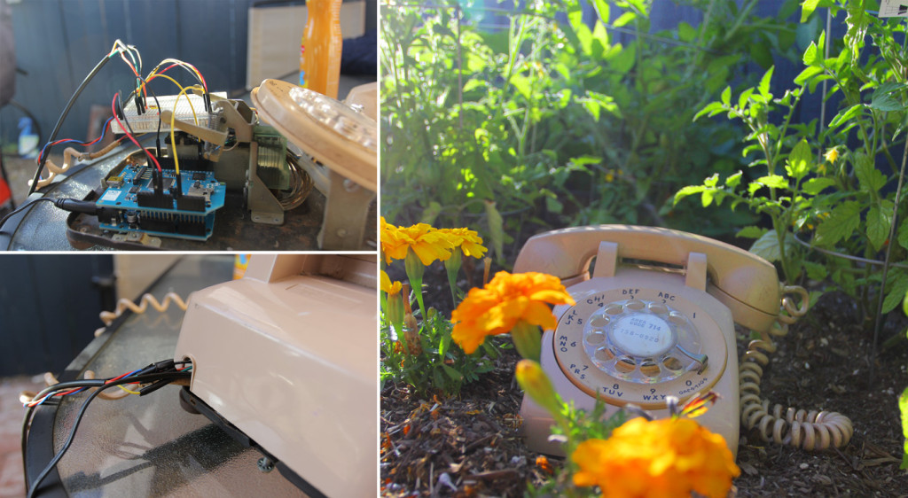
For this last step feel free to have fun. All you need to remember is that you need to protect the electronics from the environment. In my case I found an old rotary telephone and used that to house the electronics.
Of course if the phone casing isn’t realistic you can always use a 2-liter bottle or anything that can be made to be waterproof. I hope that you have fun with this project. Be sure to hit me up on email or twitter if you have any questions or just want to chat about the inevitable enslavement of humans by giant robo-garden-phones. Happy hacking!


Related Resources
Twilio Docs
From APIs to SDKs to sample apps
API reference documentation, SDKs, helper libraries, quickstarts, and tutorials for your language and platform.
Resource Center
The latest ebooks, industry reports, and webinars
Learn from customer engagement experts to improve your own communication.
Ahoy
Twilio's developer community hub
Best practices, code samples, and inspiration to build communications and digital engagement experiences.