Build a Mute/Unmute Button for your Video Calls with a Raspberry Pi Pico and MicroPython
Time to read:
May 18, 2021
Written by
Reviewed by

I always have trouble remembering what is the Zoom keyboard shortcut to mute or unmute my audio, so I end up grabbing the mouse and clicking the button instead. While there isn’t really a problem with clicking, it feels inefficient, and that awkward silence while every other call participant is waiting for me to unmute and start speaking appears to last an eternity.
I thought it would be interesting to use my Raspberry Pi Pico microcontroller board and MicroPython to design a single-key keyboard with the only function to toggle the audio on my video calls. That way, there is no key combination to remember!
Do you want to learn how to build this project? Just follow along!
Tutorial requirements
To build this cool little gadget you will need a few hardware components, described in the following sections.
Raspberry Pi Pico microcontroller
The heart of this device is going to be a Raspberry Pi Pico microntroller. For this project it is recommended that you buy one with headers already soldered, as shown in the picture below.
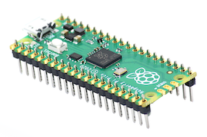
If you are handy with a soldering iron, you can buy the standard Pico, which comes without header pins, and solder them yourself.
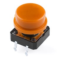
Push button
The next component that you will need to acquire is a momentary push button switch. It does not need to be exactly like the one pictured below, but you’d want it to be momentary, which means that after you release it it returns to its original state.
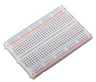
Breadboard
The easiest way to build the circuit is to do it on a breadboard. For this project a small 400 point breadboard is the perfect size.
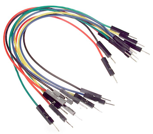
Jumper wires
The connections between the Raspberry Pi Pico and the push button will be made with jumper wires. These are short cables that have pins on the ends. The pins insert in the holes of the breadboard.
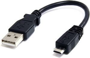
Micro-USB cable
To power your Raspberry Pi Pico you will need a USB cable. The connector on the Pico side is a micro-USB (pictured on the right side in the image below). The other end of the cable will plug into your computer, so you may need that to be a regular USB connector (as shown in the image), or maybe a USB-C connector if you have a newer computer.
Python 3
The final requirement is a Python 3 interpreter installed on your computer. If you don’t have it already, you can grab an installer for your operating system from python.org.
MicroPython vs. CircuitPython
There are two major sources of MicroPython firmware for the Raspberry Pi Pico:
- Official MicroPython builds
- CircuitPython builds from Adafruit
The MicroPython language is the same in both versions (CircuitPython is a fork of MicroPython), but there are some small variations in the functionality that is included in the releases from these two sources. CircuitPython also has an extensive library of installable drivers for many components, so even if you work with the official MicroPython, it is a good idea to keep CircuitPython in mind.
CircuitPython builds come with USB HID support included, while MicroPython builds do not. The HID (Human Interface Devices) part of the USB specification is the one that covers computer peripherals such as mice and keyboards, so for the project we intend to build, CircuitPython makes the most sense.
Installing CircuitPython on your Pico
In this section you are going to work on installing the CircuitPython firmware inside your Raspberry Pi Pico.
Visit the CircuitPython for Pico downloads page and download the latest version of the firmware to your computer. This is a file that ends with a .uf2 file extension.
Now comes the fun part. Take the USB cable and plug the USB or USB-C end into your computer. Do not plug the micro-USB end to your Pico just yet.
Grab your Pico and locate the BOOTSEL button.
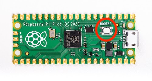
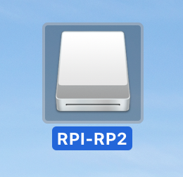
Press the button, and while you keep it pressed, plug the micro-USB end of the USB cable to power your device. In a second or two a new disk drive labeled RPI-RP2 will appear on your computer. You can release the BOOTSEL button when you see it.
To install CircuitPython, drag and drop the .uf2 file that you downloaded earlier inside this disk drive. As soon as the file transfers, the drive will disappear and the device will reboot itself. On some computers you may get a warning about the drive being disconnected without properly ejecting it. You can ignore this warning.
After your device reboots and loads the CircuitPython firmware, a new disk drive with the label CIRCUITPY should appear on your computer.
To verify that your installation was successful, create a file with the name code.py on your computer and enter the following code in it:
This code blinks the LED that is installed on the Pico board three times. While the Pico is still connected to your computer, drag and drop the code.py file to the CIRCUITPY volume. If there is a code.py file already on the disk first make sure it does not have anything you care about, and then replace it with this version.
The Pico will detect that the code.py file has been updated, will reboot itself, and run the code. You should see the LED, which is near the micro-USB connector, blink three times.
Congratulations, you have successfully installed CircuitPython on your Pico!
Installing CircuitPython libraries
While the low-level support for HID devices is bundled with the CircuitPython build, the HID protocol used by keyboards is fairly complex. Lucky for us, the Adafruit CircuitPython library includes a high-level HID interface that allows an application to emulate a keyboard, a mouse or a gamepad.
The first step to install a library is to download the CircuitPython library bundle to your computer.
Visit the CircuitPython Library Bundle page and download the latest version of the bundle to your computer. There are three downloads associated with the library bundle, all of them .zip files:
- The compiled “Bundle”
- The MicroPython source code for the bundle library
- Example code
What we need for this tutorial is the first of the three downloads, which includes the compiled MicroPython code for all the Adafruit libraries. When you download the bundle zip file, make sure that the version matches the version of CircuitPython that you installed on your Pico.
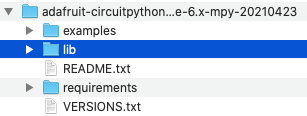
Use your favorite zip extraction tool to expand the contents of the downloaded bundle file. Inside the top-level folder you will find a lib subdirectory:
Inside lib, you will find a really large number of files and subdirectories. Look for a subdirectory with the name adafruit_hid. This is the library that we need to install on the Pico.
Open the CIRCUITPY disk drive, and create a lib directory (if it doesn’t exist yet). Then drag and drop the adafruit_hid directory inside lib. The structure of your Pico disk should now look like the following:
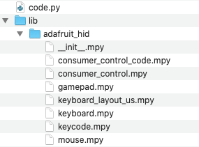
The .mpy files that you see in the adafruit_hid directory are compiled MicroPython files that are optimized to save space in your device’s file system. As such, these are not files that you can open and view in a text editor. To inspect the source code for this library you have to download the source code bundle.
The CircuitPython REPL
Like the standard Python language, MicroPython and CircuitPython come with a REPL, where you can enter statements and have them evaluated interactively. The CircuitPython REPL can be accessed from your computer while the device is connected with the USB cable.
Identifying the Pico serial device
The Pico device appears as a USB serial port device on your computer, so the first task is to figure out which of possibly several serial ports installed on your computer is the one that is connected to your board.
If you are using a Mac OS computer, the name of the Pico serial device should be /dev/tty.usbmodem<n>, where <n> is a number. To find out what the complete name of your serial device is, connect the Pico to your computer and then look in the /dev directory for files with this pattern:
On a Linux computer the device name may vary, but it usually has the format /dev/ttyACM<n>, where <n> is a number, likely 0. You can use the lsusb command to list all the USB attached devices. If you can’t identify which device is the one that maps to the Pico, you can run this command two times, once with the Pico plugged in and another one without, then see which device disappeared in the second run.
On a Windows computer the device name will have the format COM<n> where <n> is a number. You can open the Device Manager in the Control Panel and look under “Ports (COM & LPT)” for the list of serial devices. If you cannot identify which of the devices listed there is your Pico, unplug it from USB and check the list again to find which one is now missing.
Great, now you know what serial device your computer is using to connect to the Pico microcontroller.
Using mpfshell
The Pico behaves like a standard serial device, so it can be accessed with any serial terminal program available for your operating system. In this article you are going to use a tool called mpfshell, a tool that is designed to connect to and manage MicroPython microcontroller boards.
Open a terminal window in your computer and create a new directory where you will store your Pico project:
Create and activate a Python virtual environment. If you are using a Mac or Linux computer, do it as follows:
On a Windows computer, use the following commands:
Make sure that the Python virtual environment is activated by checking that your command prompt was modified to include a (venv) prefix.
Next install the mpfshell tool in your virtual environment:
Make sure the Pico is still connected to your computer with the USB cable, and then execute the following command to connect to it from your computer:
Make sure to replace <your-pico-serial-device> with the serial device name assigned to your Pico in the command above. If you are doing this on a Linux or Mac computer, you do not need to include the /dev/ prefix. For example, on my Mac computer the command that I use is:
On Windows, assuming the Pico is connected to COM3, the command would be:
The output of mpfshell should look as follows:
The command should end with a new prompt. Type help in this prompt to see all the commands mpfshell supports:
For now, let’s concentrate on the repl command, which starts an interactive shell on your Pico device:
Does this look familiar? If you’ve ever used a Python REPL you will surely recognize the >>> prompt. You can now enter Python statements, exactly like you would in a Python shell running on your computer. But keep in mind that any statements that you enter in this shell will be executed by the Pico board. Your computer is just acting as a dumb terminal.
To exit the CircuitPython shell, press Ctrl-] and that will bring you back to the mpfshell prompt. Then press Ctrl-D at the mpfshell prompt to exit back to your terminal.
If all you want to do is access the MicroPython REPL, then you can skip the intermediate step of the mpfshell prompt by adding -c repl at the end of the mpfshell command:
Building the circuit
We’ve made some good progress on the software front, so now it is time to concentrate on the hardware.
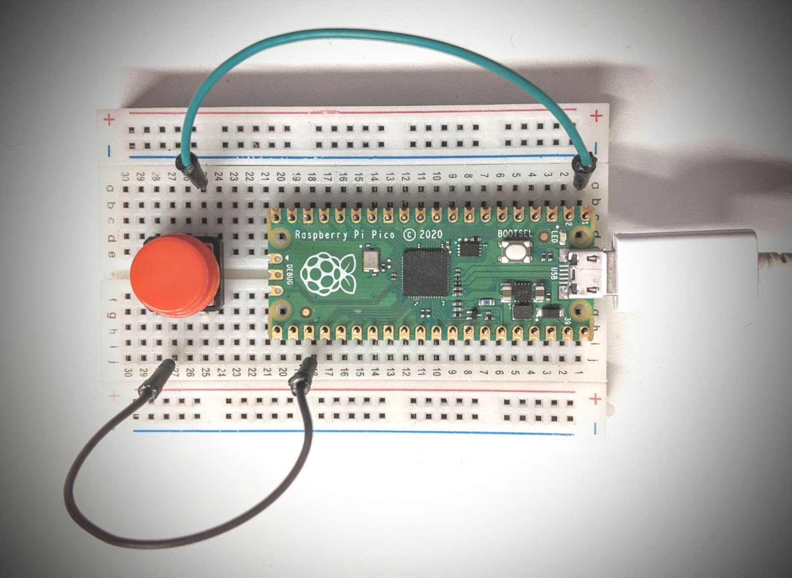
The following diagram shows how to wire the push button to the Pico using two jumper wires. We’ll go over these connections step-by-step to make sure you do it correctly.
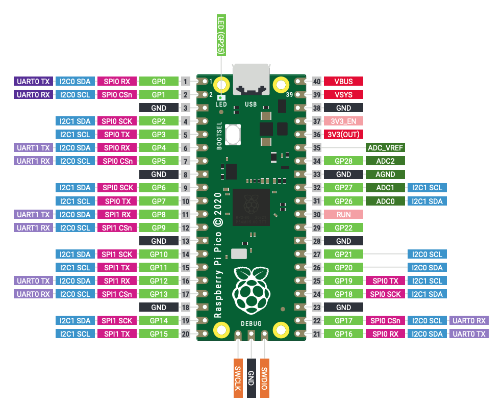
In addition to the actual wiring diagram, below you can see the pin layout of the Raspberry Pi Pico. You do not need to fully understand this diagram, but it is good to have it present and use it as a reference.
Positioning the breadboard
To begin, position your breadboard in landscape orientation, with the numbers printed on it increasing from the right to the left. For this project we are going to use the 10 rows of holes, highlighted below:
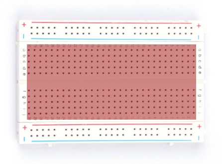
This part of the breadboard has 30 columns of holes, numbered 1 to 30 starting from the right. The five rows in the upper half are labeled a to e, while the five rows in the bottom half are labeled f to j.
On any given column, the group of 5 vertical holes (either in the top or in the bottom halves) are all internally connected to each other, and this is what makes it easy to make connections between components, as you will soon see.
Installing the Raspberry Pi Pico on the breadboard
Take the Raspberry Pi Pico with the micro-USB port pointing to the right, and carefully align the header pins with the breadboard holes. You want the right-most top and bottom pins of the Pico to match the 1c and 1h holes. Once you have it in the right position, gently press on the board to allow the pins to go in as far as they can.
It is important that the board is vertically centered on the breadboard surface, which should leave the a and b rows of holes visible right above it, and the i and j rows below it. These two rows of holes will allow us to make connections to the terminals of the Pico board.
Installing the push button
The next step is to insert your push button somewhere in the free part of the breadboard, to the left of the Pico board. For this you need to be very careful and understand how your push button’s connectors work.
Push buttons have two terminals, but many models (like the one I’m using) come with each terminal doubled, so while there are still two actual connections, there are four physical pins.
Before you install the button on the breadboard you need to identify the pairs of pins that go together. If you have the same style of push button, when you orient the button so that there are two pins on the top and two on the bottom, the two left-side pins are connected to one of the terminals, and the two right-side pins are on the other. To connect this button you have to pick one of the pins on the left and one on the right.
For convenience when wiring, the button should be installed on the breadboard in such a way that the two terminals (or the two terminal groups) end up on different columns on the breadboard. In the case of a button with double terminals, you can position the two paired terminals above and below the middle line of the breadboard respectively, as I’ve done in the picture above.
The installation that I used has the button’s connectors on columns 25 and 27 of the breadboard, with the terminals on rows d and g. To connect this button you will need a wire in any of the open holes in column 25 (top or bottom, whatever is most convenient) and another in any of the holes in column 27.
Installing the jumper wires
The last wiring step is to connect the Pico to the button with two jumper wires.
Take one of the wires, and plug one of the ends in the hole 1a. This hole is connected to pin 1 of the Pico board, also known as GP0. This is one of the Pico’s GPIO (General Purpose Input/Output) pins, used for connections to other devices.
Insert the other end of the wire next to one of the button’s connectors. It doesn't really matter which one, it can be any of them. I connected it on the 25a hole, which is connected to the right-side terminals of the push button.
The second wire is connected to the Pico on the bottom side, on the 18j hole, which is connected to pin 23. According to the pin diagram this pin is a “ground” pin, or GND, which means that when anything is connected to it, it attracts electricity towards itself.
Connect the other end of the second wire to the second button terminal. In my case I inserted this end of the wire on the 27j breadboard hole, which is in the same group as the lower left-side button terminal.
Testing the push button
The hardware circuit is now complete, so for the next step you are going to write a short CircuitPython application that prints something when the button is pressed.
Remember the code.py file you wrote at the beginning of this tutorial, which made the LED in the Pico board blink three times? Let’s extend that program to also blink the LED when the button is pressed.
Open code.py on your text editor or IDE and copy the following code to it, replacing the previous contents of the file. The parts of this code that are new are highlighted.
With this version we are initializing two variables gp0 and led. These are digital pins of the Pico board that can function as inputs or outputs. We are using the direction attribute to indicate that the gp0 pin is an input pin and the led pin is an output pin. That means that the expression gp0.value will give us the state of the GP0 pin (a True or False value), while setting led.value to True or False will operate the LED.
The gp0 pin is also configured as a “pull-up” pin. Pull-up pins have some special wiring (that is implemented internally by the Pico board). These are often used to read buttons or other types of switches. The idea is that a pull-up pin is configured internally to have a charge, which means that it reads as a high or True value when it is not connected to anything.
In our circuit, the GP0 pin is connected to a GND (ground) pin with the button in between. When the button is pressed, the connection between these two will be made, and the charge in the GP0 pin will drain towards the ground, changing the value of the pin to low or False. In other words, this pin will have a default value of True, and only when the button is pressed the value will change to False.
You’ve seen the for-loop in the first version of this file. This loop blinks the LED three times. While this isn’t necessary for our purposes, I find it useful as a visual signal that the board is actually running the code.
The while-loop that follows starts with an inner while-loop that blocks while gp0.value is True. This is the high state for the GP0 pin, which corresponds to the button not being pressed.
As soon as the button is pressed gp0.value will change to False and that first inner while-loop will exit. At this point we print a debugging message, we turn the LED on, wait for half a second, and then turn it off again.
The last part of the outer while-loop is another inner while-loop that waits for the GP0 pin to go back to the high or True value. The idea here is that we want to prevent duplicate firings of the button, so we want to wait for the user to release the button before we end the loop iteration and go back to the top to wait for another press.
Save code.py locally on your computer, and then drop the file on the CIRCUITPY disk drive. A moment later the board will reboot and execute the code automatically. You will know when the board is ready because you will see the LED blink three times. If you do not see the LED blink, it could be because CircuitPython is still inside a shell sessio, so it is not rebooting automatically when code.py changes. You can disconnect it from power and connect it again to make sure it runs your code.
After the LED does its blinking dance, try pressing the button to see if the LED reacts to it.
Does the LED blink as a response to a button press? Great! You are ready to move on to the last step of the tutorial. If the LED does not blink, then something isn’t working, so you’ll need to debug the problem.
To debug this application, start a REPL with mpfshell:
Now press Ctrl-D to force the Pico to do a soft-reboot and run code.py from scratch. At this point the code will run while you are connected on the terminal, so if there are any errors they’ll be printed to the screen. This should help you debug any issues.
Emulating a keyboard
We are now very close to having this project completed. The last change we need to make to our code.py file is to emit a key to the computer through the USB connection. The computer will be fooled into thinking the key is coming from an actual USB keyboard.
Here is the final code.py, with the changes from the previous version highlighted:
The USB HID support in CircuitPython requires us to import three new packages:
usb_hid: the low-level HID supportadafruit_hid.keyboard.Keyboard: the high-level keyboard support classadafruit_hid.keycode.Keycode: key constants
In addition to the gp0 and led variables, we now add keyboard, which is initialized as an instance of the Keyboard class from the Adafruit HID library. This object is what will make the Pico board appear to the computer as a USB keyboard.
To send a key to the computer, we use the keyboard.send() method. Depending on the use you intend to give this application, the key that you send might need to change. The Zoom application uses the Cmd+Shift+A keyboard shortcut to toggle the audio on Mac, so this is what I implemented:
In CircuitPython the Mac’s Command key is called Keycode.GUI.
For a Windows computer, Zoom uses the Ctrl-A shortcut, so you would use this instead:
You can change the key combination to be anything you want. And if you want to test this without using Zoom or any other application, you can just make the program output a letter A:
To test the application this way, make sure you open a text editor so that you can see the letter appear as you push the button.
Next steps with the Raspberry Pi Pico
I hope you had fun working on this project, and that this motivates you to continue working with MicroPython and microcontrollers.
Are you interested in more articles about the Raspberry Pi Pico? I’ve also written an introductory tutorial that uses the official MicroPython build instead of CircuitPython.
I’d love to see what you build!
Miguel Grinberg is a Principal Software Engineer for Technical Content at Twilio. Reach out to him at mgrinberg [at] twilio [dot] com if you have a cool project you’d like to share on this blog!


Related Resources
Twilio Docs
From APIs to SDKs to sample apps
API reference documentation, SDKs, helper libraries, quickstarts, and tutorials for your language and platform.
Resource Center
The latest ebooks, industry reports, and webinars
Learn from customer engagement experts to improve your own communication.
Ahoy
Twilio's developer community hub
Best practices, code samples, and inspiration to build communications and digital engagement experiences.