Programming the Raspberry Pi Pico Microcontroller with MicroPython
Time to read:
February 06, 2021
Written by
Reviewed by

With the release of the Raspberry Pi Pico, the Raspberry Pi Foundation has expanded its product offering beyond their highly successful line of mini-computers and went even smaller by entering the microcontroller market.
Unlike the Raspberry Pi, which functions as a general purpose computer and runs the popular Linux operating system, the Pico is a much more primitive device that lacks a central operating system and can only be programmed to perform specific tasks or control connected peripherals, usually as part of an embedded system or Internet of Things device.
While most microcontrollers can only be programmed in C or C++, the Pico also offers support for MicroPython, a slimmed down version of Python that is designed specifically for small devices. This makes it a great choice for beginners who want to design their own devices but don’t have the patience or interest to learn low-level programming.
In this article you are going to learn how to set up and program your Pico with MicroPython. Don’t have one yet? They sell for $4 USD so buy one (or two!) and follow along.
Requirements
To follow this tutorial you will need the following items:
- A Raspberry Pi Pico microcontroller. You can find out where to buy one in your region here.
- A computer with one USB or USB-C available port. Windows, Mac and Linux are all good!
- A USB to micro-USB cable. These are used as charger cables for many cell phones, so you may already have one. Here is a link to one if you need to buy it or see a picture. If your computer has USB-C ports, then you will also need a USB to USB-C adapter.
- Python 3.6+ installed on your computer. If you don’t have it, you can download an installer.
Installing MicroPython on your Pico
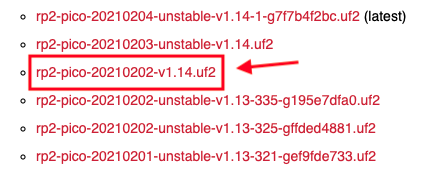
Before you can program the Pico with MicroPython, this language needs to be installed on the microcontroller board. You can visit the MicroPython for Pico Downloads page to find the current version. You will find a list of stable and unstable builds. From the list, find the most recent stable build and download it to your computer. This is going to be a file with a .uf2 extension.
Now comes the fun part. Take the USB to Micro-USB cable and plug the USB end to your computer.
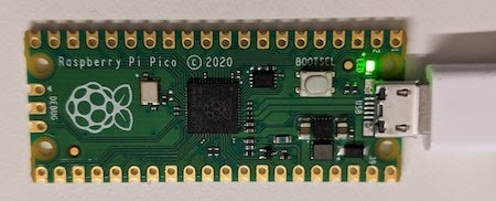
Next, grab your Pico and locate the BOOTSEL button.
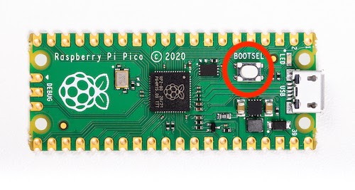
Press the button, and while you keep it pressed, plug the micro-USB end of your cable into your Pico (the micro-USB connector is seen on the right side in the above picture). In a second or two a new disk drive will appear on your computer. You can release the button when you see it.
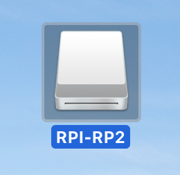
To install MicroPython, drag and drop the .uf2 file that you downloaded earlier inside this disk drive. As soon as the file transfers, the drive will disappear and the device will reboot itself. On some computers you may get a warning about the drive being disconnected without properly ejecting it. You can ignore this warning.
Congratulations, you have successfully installed MicroPython on your Pico!
Accessing the MicroPython REPL
Like the standard Python language, MicroPython comes with a REPL, where you can enter statements and have them evaluated interactively. The MicroPython REPL can be accessed from your computer while connected with the USB cable.
The Pico should appear as a serial port device on your computer, so the next task is to figure out which of possibly several serial ports installed on your computer is the one that is connected to your microcontroller, and this varies depending on which operating system you are using:
- If you are using a Mac computer, then the name of the Pico serial device is
/dev/tty.usbmodem0000000000001. - On a Linux computer the device name may vary, but it usually has the format
/dev/ttyACM<n>, where<n>is a number, likely 0. You can use thelsusbcommand to list all the USB attached devices. If you can’t identify which device maps to the Pico, you can unplug it from the computer and runlsusbagain to see which device is now missing. - On a Windows computer the device name will have the format
COM<n>where<n>is a number. You can open the Device Manager of the Control Panel and look under “Ports (COM & LPT)” for the list of serial devices. If you cannot identify which of the devices listed there is your Pico, unplug it from USB and check the list again to find which one is now missing.
Great, now you know what serial device your computer is using to connect to the Pico microcontroller.
The Pico behaves like a standard serial device, so it can be accessed with any serial terminal program available for your operating system. In this article you are going to use rshell, a tool written in Python that is designed to connect to and manage MicroPython microcontroller boards.
Open a terminal window in your computer and create a new directory where you will store your Pico experiments:
Create and activate a Python virtual environment. If you are using a Mac or Linux computer, do it as follows:
On a Windows computer, use the following commands:
Make sure that the Python virtual environment is activated by checking that your command prompt was modified to include a (venv) prefix.
Next install the rshell tool in your virtual environment:
Make sure the Pico is still connected to your computer with the USB cable (you will not see a disk drive now), and then execute the following command to connect to it from your computer:
Make sure to replace <your-pico-serial-device> with the serial device name assigned to your Pico in the command above. For example, on a Mac computer the actual command is:
On Windows, assuming the Pico is connected to COM3, the command would be:
The output of rshell should look as follows:
The command should end with a new prompt. Type help in this prompt to see all the commands rshell supports:
For now, let’s concentrate on the repl command, which starts a MicroPython interactive shell on your Pico device:
Does this look familiar? If you’ve ever used a Python REPL you will surely recognize the >>> prompt. You can now enter Python statements, exactly like you would in a Python shell running on your computer. But keep in mind that MicroPython runs on the Pico board and your computer is acting as a dumb terminal.
To exit the MicroPython shell, press Ctrl-X and that will bring you back to the rshell prompt. Then press Ctrl-D at the rshell prompt to exit back to your terminal.
If all you want to do is access the MicroPython REPL, then you can skip the intermediate step of the rshell prompt by adding repl at the end of the rshell command:
Programming the Pico
To work with a microcontroller such as the Pico, you basically have to issue read or write requests to any of its I/O pins. Some of the pins in the Pico are available for you to connect external devices, while some others are internally connected. Below you can see a diagram that shows the functions of all the I/O pins in the board:
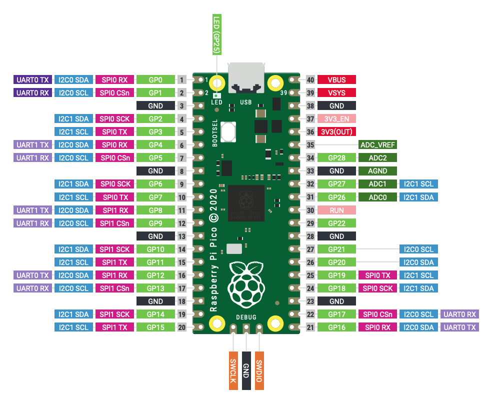
You can find a higher resolution version of this diagram in PDF format here. As you can see, most pins have several functions.
In this section you will learn how to work with two components that are included in the Pico board: the LED, which you can see labeled as GP25 at the top of the above diagram, and a temperature sensor, which for some strange reason has not been included in this diagram.
Accessing the onboard LED
The LED that comes with the Pico board is connected to a pin labeled GP25. This is one of several “GPIO” or General-Purpose Input/Output pins available in the Pico board. You can recognize these pins because they are labeled with GP followed by a number.
MicroPython includes the machine module, and more specifically the machine.Pin class to access and work with GPIO pins.
Enter the MicroPython REPL and then type the following Python commands to turn the LED on:
Here you are creating a Pin object that is attached to GPIO pin 25, and specifying that this pin will be used as an output pin. The on() method sets a “high” value on the pin, which triggers the onboard LED to light up.
You can probably guess what happens if you call led.off(). Another interesting option you can try is to call led.toggle().
Obtaining a temperature reading
The temperature sensor that comes with the Pico is connected to one of a few special pins called ADCs or Analog-to-Digital Converters. The difference between a standard GPIO pin and an ADC pin is that a GPIO pin supports only two states, high and low, while an ADC pin supports a range of values, which is determined by the input voltage applied to the pin.
In the Pico, the ADC pins support 12-bits, which means that their value can go from 0 to 4095. MicroPython, however, scales the ADC values to a 16-bit range, so effectively the range is from 0 to 65535. The microcontroller runs at 3.3 V, which means that an ADC pin will return a value of 65535 when 3.3 V are applied to it, or 0 when there is no voltage. All the values in between are obtained when the voltage applied to the pin is between 0 and 3.3 V.
The ADC pins in the Pico board use their own numbering scheme instead of going by their GPIO pin number. In the pin diagram above you can see the pins labeled ADC0, ADC1, ADC2 and ADC_VREF (technically ADC3), which are the four externally accessible ADC pins. The temperature sensor does not have a physical pin in the board, but is accessed as ADC4.
The machine module provides the ADC() class to work with ADC pins. The following code can be used to read the temperature sensor from the MicroPython shell:
If you print the value of the temperature value you are going to get an integer number between 0 and 65535, as indicated above. This is not very useful as a temperature measurement, so you will probably want to convert this value either to the Celsius or Fahrenheit degree scales.
The temperature sensor works by delivering a voltage to the ADC4 pin that is proportional to the temperature. According to the specifications of this sensor, a temperature of 27 degrees Celsius delivers a voltage of 0.706 V, with each additional degree reducing the voltage by 1.721 mV, or 0.001721 V. Conversely, each degree below 27 degrees Celsius increases the voltage by the same amount. The first step in converting the 16-bit temperature is to convert it back to volts, which is done based on the 3.3 V maximum voltage used by the Pico board:
With this conversion the temperature value holds a value between 0 and 3.3. A second conversion is now necessary to bring the temperature to the Celsius scale:
And finally, if you want to use the Fahrenheit scale, there is one more conversion to be applied on the Celsius temperature:
Writing a complete application
In addition to executing little tests, the Pico can be programmed to run a complete MicroPython application when it boots.
As an example, let’s build a short application that blinks the onboard LED five times. Here is the code, which you can copy into a new file on your computer named led_blink.py:
One of the many functions the rshell command can perform to help you manage your MicroPython board is to copy files between your computer and the board’s file system. To install the above application in your Pico board so that it automatically executes when the board is powered on, you have to copy it with the name main.py, which is automatically imported at the end of the boot sequence.
To do this, start by entering the rshell prompt:
Then in the rshell prompt use the cp command to copy the file to the Pico board:
The cp command, as well as other file system based commands, use the convention that any paths that begin with /pyboard/ refer to the virtual file system set up by MicroPython inside the microcontroller board. Any paths or filenames that do not have this prefix are assumed to reference your computer’s file system.
The cp command above copies the local led_blink.py file from your computer to the root directory of the Pico file system with the name main.py.
After you copy the file, exit rshell and then power cycle your Pico by unplugging it from USB and then plugging it again. You should now see the LED blink five times! The main.py file is now part of the boot sequence of the board, so it will also run if you trigger a soft reboot by pressing Ctrl-D in a REPL session.
Feel free to experiment by changing the above application to blink the LED in different patterns. After making changes to the code in your computer remember to use the cp command in rshell to update the copy stored in the Pico.
When you are done playing with the application you can remove the file from the board’s file system with the rm command:
Are you wondering why I named the local file led_blink.py instead of using the main.py name that has to be used in the Pico’s file system? The reason is that in rshell it is too easy to make a mistake and run rm main.py when you really wanted to run rm /pyboard/main.py. Using different names ensures that you don’t accidentally delete your local file.
Conclusion
I hope this was a fun and easy introduction to programming the Pico microcontroller with MicroPython!
Are you interested in more articles about the Raspberry Pi Pico? I’ve also written a fun tutorial for a mute/unmute physical button that you can use during your video conference calls!
This article only explored a tiny fraction of the wide range of applications that can be built with this microcontroller. There are a number of compatible devices such as displays, LED lights, buttons and sensors that can be connected to the Pico through its GPIO pins to help you get the most out of it. A good place to start when looking for accessories for your Pico is the Pimoroni Pico store.
I can’t wait to see what you build!
Miguel Grinberg is a Python Developer for Technical Content at Twilio. Reach out to him at mgrinberg [at] twilio [dot] com if you have a cool Python project you’d like to share on this blog!


Related Resources
Twilio Docs
From APIs to SDKs to sample apps
API reference documentation, SDKs, helper libraries, quickstarts, and tutorials for your language and platform.
Resource Center
The latest ebooks, industry reports, and webinars
Learn from customer engagement experts to improve your own communication.
Ahoy
Twilio's developer community hub
Best practices, code samples, and inspiration to build communications and digital engagement experiences.